|
|
|
PDF ISL97672A Data sheet ( Hoja de datos )
| Número de pieza | ISL97672A | |
| Descripción | 6-Channel LED Driver | |
| Fabricantes | Intersil | |
| Logotipo | ||
Hay una vista previa y un enlace de descarga de ISL97672A (archivo pdf) en la parte inferior de esta página. Total 16 Páginas | ||
|
No Preview Available !
NROETCROEMCMOEMNMDEEISNDLDR9E7ED6P7FL2OABRCENMEEWNDTEPSAIRGTNS
6-Channel LED Driver with Ultra Low Dimming
Capability
ISL97672A
The ISL97672A is an integrated 6-channel power LED driver for
LCD backlight applications. The ISL97672A is capable of
driving LEDs with input from 4.5V to 26.5V and maximum
output up to 45V.
The ISL97672A employs an adaptive boost switching
architecture that allows Direct PWM dimming with dimming
duty cycle as low as 0.007% at 200Hz or 0.8% at 20kHz. PWM
Dimming frequency can be as high as 30kHz.
The ISL97672A employs the dynamic headroom control that
monitors the highest LED forward voltage string for output
regulation to minimize headroom voltage and power loss in a
typical multi-string operation. Typical current matching between
channels is ±0.7%.
The ISL97672A incorporates extensive protection functions
that flag whenever a fault occurs. The protections include
string-open and short-circuit detections, OVP, OTP, and an
optional output short-circuit protection with external fault
disconnect switch.
The ISL97672A is offered in a compact 20 Ld QFN 3x4 package
and can operate in ambient temperatures of -40°C to +85°C.
Features
• 6 x 50mA Channels
• 4.5V to 26.5V Input
• 45V Output Max
• Adaptive Boost Switching Architecture
• Direct PWM Dimming with Dimming Linearity of
0.007%~100% at 200Hz or 0.8%~100% <20kHz
• Adjustable 200kHz to 1.4MHz Switching Frequency
• Dynamic Headroom Control
• Fault Protections with Latched Flag Indication
- String Open/Short Circuit
- OVP
- OTP
- Optional Output Short-Circuit Fault Protection Switch
• Current Matching ±0.7%
• 20 Ld 3x4 QFN Package
Applications
• Notebook Displays LED Backlighting
• LCD Monitor LED Backlighting
• Multi-Function Printer Scanning Light Source
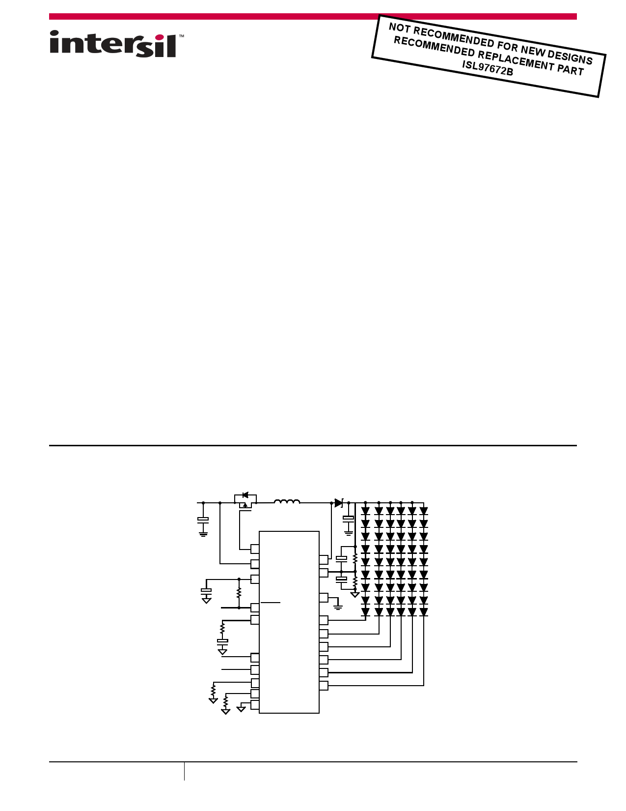
Typical Application Circuit
VIN = 4.5~26.5V
Q1(OPTIONAL)
VOUT = 45V*, 6 x 50mA
ISL97672A
1 FAULT
2 VIN
4 VDC
LX 20
OVP 16
6 FLAG
18 COMP
3 EN
5 PWM
17 RSET
8 FSW
9 AGND
PGND 19
CH0 10
CH1 11
CH2 12
CH3 13
CH4 14
CH5 15
*VIN > 12V
FIGURE 1. ISL97672A TYPICAL APPLICATION DIAGRAM
November 22, 2013
FN7710.3
1
CAUTION: These devices are sensitive to electrostatic discharge; follow proper IC Handling Procedures.
1-888-INTERSIL or 1-888-468-3774 | Copyright Intersil Americas LLC 2011, 2013. All Rights Reserved
Intersil (and design) is a trademark owned by Intersil Corporation or one of its subsidiaries.
All other trademarks mentioned are the property of their respective owners.
1 page 
ISL97672A
Electrical Specifications All specifications are tested at TA = +25°C, VIN = 12V, EN = 5V, RSET = 20.5kΩ, unless otherwise noted. Boldface
limits apply over the operating junction temperature range, -40°C to +85°C.
PARAMETER
DESCRIPTION
CONDITION
MIN MAX
(Note 8) TYP (Note 8) UNIT
REGULATOR
VDC
IVDC_STBY
LDO Output Voltage
Standby Current
VIN > 6V
EN = 0V
4.55
4.8
5V
5 µA
VLDO
ENLow
ENHi
tENLow
BOOST
VDC LDO Droop Voltage
Guaranteed Range for EN Input Low Voltage
Guaranteed Range for EN Input High Voltage
EN Low Time Before Shut-down
VIN > 5.5V, 20mA
20 200 mV
0.5 V
1.8 V
30.5
ms
SWILimit
rDS(ON)
SS
Boost FET Current Limit
Internal Boost Switch ON-Resistance
Boost Soft-start Time
TA = +25°C
100% LED Duty Cycle
1.5 2.0 2.7 A
235 300 mΩ
7 ms
Eff_peak
Peak Efficiency
ΔIOUT/ΔVIN
Dmax
Line Regulation
Boost Maximum Duty Cycle
Dmin
Boost Minimum Duty Cycle
fS Minimum Switching Frequency
fS Maximum Switching Frequency
ILX_leakage
LX Leakage Current
CURRENT SOURCES
VIN = 12V, 72 LEDs, 20mA
each, L = 10µH with DCR
101mΩ, TA = +25°C
VIN = 12V, 60 LEDs, 20mA
each, L = 10µH with DCR
101mΩ, TA = +25°C
FSW = 600kHz
FSW = 1.2MHz
FSW = 600kHz
FSW = 1.2MHz
RFSW = 200kΩ
RFSW = 33kΩ
LX = 45V, EN = 0
92.9
%
90.8
%
0.1
90
81
175
1.312
200
1.50
9.5
17
235
1.69
10
%
%
%
%
%
kHz
MHz
µA
IMATCH
Channel-to-Channel Current Matching
IACC
Vheadroom20
Vheadroom33
VRSET
ILEDmax
Current Accuracy
Dominant Channel Current Source Headroom
at IIN Pin measured with ILED= 20mA
Dominant Channel Current Source Headroom
at IIN Pin measured with ILED= 33mA
Voltage at RSET Pin
Maximum LED Current per Channel
FAULT DETECTION
RSET =20.5kΩ
(IOUT = 20mA)
ILED = 20mA
TA = +25°C
ILED = 33mA
TA = +25°C
RSET = 20.5kΩ
VIN = 12V, VOUT = 45V,
FSW = 1.2MHz, TA = +25°C
±0.7
±1.0
%
-1.5
560
(Note 9)
1.2
500
(Note 9)
710
1.22
50
+1.5
860
(Note 9)
1.24
%
mV
V
mA
VSC Channel Short Circuit Threshold
PWM Dimming = 100%
7.5 8.2
V
Temp_shtdwn Over-Temperature Shutdown Threshold
150 °C
Temp_Hyst Over-Temperature Shutdown Hysteresis
23 °C
VOVPlo
Overvoltage Limit on OVP Pin
1.199
1.24
V
5 FN7710.3
November 22, 2013
5 Page 
ISL97672A
If R1 and R2 are chosen such that the OVP level is set at 40V,
then VOUT is allowed to operate between 25.6V and 40V. If the
VOUT requirement is changed to an application of six LEDs of 21V,
then the OVP level must be reduced. Users should follow the
VOUT = (64% ~100%) OVP level requirement; otherwise, the
headroom control will be disturbed such that the channel voltage
can be much higher than expected. This can sometimes prevent
the driver from operating properly.
The resistances should be large, to minimize power loss. For
example, a 1MΩ RUPPER and a 30kΩ RLOWER sets OVP to 41.9V.
Large OVP resistors also allow COUT to discharge slowly during the
PWM Off time. Parallel capacitors should also be placed across
the OVP resistors such that RUPPER/RLOWER = CLOWER/CUPPER.
Using a CUPPER value of 30pF is recommended. These capacitors
reduce the AC impedance of the OVP node, which is important
when using high-value resistors. For example, if RUPPER/RLOWER
= 33/1, then CUPPER/CLOWER = 1/33 with CUPPER = 100pF and
CLOWER = 3.3nF
Undervoltage Lock-out
If the input voltage falls below the UVLO level, the device stops
switching and is reset. Operation restarts only when VIN returns
to the normal operating range.
Input Overcurrent Protection
During a normal switching operation, the current through the
internal boost power FET is monitored. If the current exceeds the
current limit, the internal switch is turned off. Monitoring occurs
on a cycle-by-cycle basis in a self-protecting way. Additionally, the
ISL97672A monitors the voltage at the LX and OVP pins. At start-
up, the LX pins inject a fixed current into the output capacitor.
The device does not start unless the voltage at LX exceeds 1.2V.
The OVP pin is also monitored such that if it rises above and
subsequently falls below 20% of the target OVP level, the input
protection FET is also switched off.
Over-Temperature Protection (OTP)
The ISL97672A includes two over-temperature thresholds. The
lower threshold is set to +130°C. When this threshold is reached,
any channel that is outputting current at a level significantly below
the regulation target is treated as “open circuit” and is disabled
after a time-out period. This time-out period is 800µs when it is
above the lower threshold. The lower threshold isolates and
disables bad channels before they cause enough power
dissipation (as a result of other channels having large voltages
across them) to hit the upper temperature threshold.
The upper threshold is set to +150°C. Each time this threshold is
reached, the boost stops switching, and the output current
sources switch off. Once the device has cooled to approximately
+100°C, the device restarts, with the DC LED current level
reduced to 75% of the initial setting. If dissipation persists,
subsequent hitting of the limit causes identical behavior, with the
current reduced in steps to 50% and finally 25%. Unless disabled
via the EN pin, the device stays in an active state throughout.
For complete details of fault protection conditions, see Figure 20
and Table 1.
VIN
/FLAG
DRIVER
FAULT
IMAX ILIMIT
LOGIC
O/P
SHORT
FET
DRIVER
LX
LX
OVP
VOUT
FAULT FLAG
VSC
CH0
CH5
THRM
SHDN
OTP
FAULT
DETECT
LOGIC
VSET
PWM/OC0/SC0
PWM
GENERATOR
REF
T2
TEMP
SENSOR
T1
Q0 VSET
PWM/OC5/SC5
FIGURE 20. SIMPLIFIED FAULT PROTECTIONS
11
Q5
FN7710.3
November 22, 2013
11 Page | ||
| Páginas | Total 16 Páginas | |
| PDF Descargar | [ Datasheet ISL97672A.PDF ] | |
Hoja de datos destacado
| Número de pieza | Descripción | Fabricantes |
| ISL97672 | 6-Channel LED Driver | Intersil |
| ISL97672A | 6-Channel LED Driver | Intersil |
| ISL97672B | 6-Channel LED Driver | Intersil |
| Número de pieza | Descripción | Fabricantes |
| SLA6805M | High Voltage 3 phase Motor Driver IC. |
Sanken |
| SDC1742 | 12- and 14-Bit Hybrid Synchro / Resolver-to-Digital Converters. |
Analog Devices |
|
DataSheet.es es una pagina web que funciona como un repositorio de manuales o hoja de datos de muchos de los productos más populares, |
| DataSheet.es | 2020 | Privacy Policy | Contacto | Buscar |