|
|
|
PDF ISL1539A Data sheet ( Hoja de datos )
| Número de pieza | ISL1539A | |
| Descripción | Dual Port VDSL2 Line Driver | |
| Fabricantes | Intersil | |
| Logotipo | ||
Hay una vista previa y un enlace de descarga de ISL1539A (archivo pdf) en la parte inferior de esta página. Total 23 Páginas | ||
|
No Preview Available !
Dual Port VDSL2 Line Driver
ISL1539A
The ISL1539A provides 4 internal wideband op amps
intended to be used as two pairs of differential line
drivers. The ISL1539A’s high bandwidth, 240MHz, and
ultra low distortion, -89dBc @ 1MHz, 2VP-P, support the
demanding MTPR requirements of emerging VDSL2 line
driver designs. Less demanding requirements can be met
at very low quiescent powers using the supply current
adjustment features.
Each of the 4 internal op amps is a wideband current
feedback amplifier offering very high slew rate intrinsic to
that design using low quiescent current levels. Each of
the two pair of amplifiers (ports) can also be power
optimized to the application using two external quiescent
control logic pins. Full power is nominally 27.2mA/port
with options of medium power cutback to 23mA/port, a
low power condition at 13.5mA/port, and an off state at
<0.5mA/port. Added quiescent power flexibility is
provided through an external IADJ pin. Grounding the pin
gives the nominal currents listed above while inserting a
resistor from this pin to ground can be used to scale each
of the settings downward.
High power push/pull line driver applications as
illustrated in the example below are best supported using
a low headroom, high output current device. On ±12V
supplies, the ISL1539A offers a 1.1V headroom with
>360mA peak output current. Driving differentially this
gives >41.8VP-P swing to as low as 58Ω differential load.
High SFDR operation is also supported for supplies as low
as ±7.5V. Intended to be used as differential pairs, this
two port device includes special circuitry to minimize
common mode loop peaking while also reducing the
common mode output noise spectrum. That circuitry
links the two sides of each port, precluding their
application as individual amplifiers.
Features
• 360mA Output Drive Capability
• 41.8VP-P Differential Output Drive into 100Ω
• -89dBc THD @ 1MHz 2VP-P
• -65dBc MTPR (VDSL 8b Profile)
• High Slew Rate of 3000V/µs Differential
• Bandwidth (240MHz @ AV-DIFF = 10)
• Supply Current Control Pins
• Port Separation
- 78dB @ 500kHz
- 70dB @ 1MHz
- 60dB @ 4MHz
• Pb-Free (RoHS Compliant)
Applications*(see page 21)
• 8MHz and 17MHz VDSL2 Profiles
• ADSL2+
Related Literature (see Device Info page)
• AN1325 “Choosing and Using Bypass Capacitors”
• TB426 “Characterization of the Output Protection
Circuitry of the EL1528 DSL Driver for Lightning
Surges”
TABLE 1. ALTERNATE SOLUTIONS
NOMINAL ±VCC BANDWIDTH
PART #
(V)
(MHz) APPLICATIONS
ISL1557
±6
200 VDSL
ISL1534
±12
40 ADSL2+
ISL1536
±12
50 ADSL2+
Typical Application
+12V
Rb + ¼
ISL1539A
Ro
- Rf
3.2kΩ
1:n
VI
SOURCE
Rg 711Ω
VO
LOAD
Rf
- 3.2kΩ
¼
ISL1539A
Ro
+
Rb
AV-DIFF = VO/VI = 10V/V
-12V
TYPICAL DIFFERENTIAL I/O LINE DRIVER
(1 OF 2 PORTS)
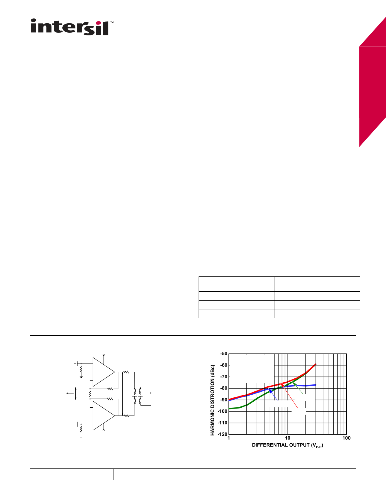
4MHz Harmonic Distortion
VS = ±12V
AV = +10
RF = 3.2kΩ
RL = 100Ω DIFF
3rd HD
2nd HD
THD
September 23, 2009
FN6916.0
1 CAUTION: These devices are sensitive to electrostatic discharge; follow proper IC Handling Procedures.
1-888-INTERSIL or 1-888-468-3774 | Intersil (and design) is a registered trademark of Intersil Americas Inc.
Copyright © Intersil Americas Inc. 2009. All Rights Reserved.
All other trademarks mentioned are the property of their respective owners.
1 page 
ISL1539A
Electrical Specifications VS = ±12V, RL= 100Ω differential, IADJ = C0 = C1 = 0V, AV = 10V/V, RF = 3.2kΩ,
TA = +25°C. Amplifier pairs tested separately unless otherwise indicated. (Continued)
PARAMETER
DESCRIPTION
CONDITIONS
MIN
TYP
MAX
UNIT
4MHz Harmonic 2nd Harmonic
Distortion
VOUT = 10VP-P-DIFF
(Note 6)
-72 dBc
3rd Harmonic
VOUT = 10VP-P-DIFF
(Note 6)
-70 dBc
THD
VOUT = 10VP-P-DIFF
(Note 6)
-68 dBc
8MHz Harmonic
Distortion
eN
2nd Harmonic
VOUT = 2VP-P-DIFF (Note 6)
3rd Harmonic
VOUT = 2VP-P-DIFF (Note 6)
THD
VOUT = 2VP-P-DIFF (Note 6)
Non-Inverting Input Voltage f = 1MHZ
Noise at each of the 4 Inputs
-83 dBc
-78 dBc
-76 dBc
4.0 nV/√Hz
+iN Non-Inverting Input Current f = 1MHZ
Noise at each of the 4 Inputs
2.7 pA/√Hz
-iN Inverting Input Current Noise f = 1MHZ
at each of the 4 Inputs
23 pA/√Hz
eN-CM
Common Mode Output Noise f = 1MHZ
at each Port Pair
90 nV/√Hz
POWER CONTROL FEATURES
VIH
Logic High Voltage
C0 and C1 inputs
VIL
Logic Low Voltage
C0 and C1 inputs
IIH0 , IIH1
Logic High Current for C0, C1 C0 = 3.3V, C1 = 3.3V
IIL0, IIL1
Logic Low Current for C0 or C1 C0 = 0V, C1 = 0V
IADJ
Input Resistance
SUPPLY CHARACTERISTICS
2.0
0.8
-5 1 +5
-17 -13 -10
500
V
V
µA
µA
Ω
Maximum Operating Supply
Voltage
±12.6
V
Minimum Operating Supply
Voltage
±7.5
V
IGND
IS+ (Full Power)
GND Pin Current per Port
Positive Supply Current per
Port
All outputs at 0V (Note 7)
All outputs at 0V, C0 = C1 = 0V, No
Load
0.2 0.4 0.5
21
27.2
31.5
mA
mA
IS+ (Medium)
Positive Supply Current per All outputs at 0V, C0 = 3.3V, C1 = 0V, 17.8
23
26.7
mA
Port
No Load
IS+ (Low)
Positive Supply Current per All outputs at 0V, C0 = 0V, C1 = 3.3V,
Port
No Load
10.4
13.5
15.6
mA
IS+ (Power-down) Positive Supply Current per All outputs at 0V, C0 = C1 = 3.3V, No
0.2
0.4
0.5
Port
Load
mA
OUTPUT CHARACTERISTICS
VOUT
IOL
Output Swing
Lightly Loaded Positive Swing
Lightly Loaded Negative Swing
Heavy Loaded Positive Swing
Heavy Loaded Negative Swing
Linear Output Current
RL-DIFF = No Load
RL-DIFF = 100Ω
RL-DIFF = 100Ω
RL-DIFF = 60Ω
RL-DIFF = 60Ω
RL = 25Ω, f = 100kHz, THD = -60dBc
±10.7
+10.3
+9.4
±10.9
+10.5
-10.4
+9.8
-9.7
±360
-10.2
-9.3
V
V
V
V
V
mA
5 FN6916.0
September 23, 2009
5 Page 
ISL1539A
Typical Performance Curves
VCC = ±12V, RF = 3.2kΩ, GD = 10V/V (differential), RLOAD = 100Ω, TA ≈ +25°C, C0 = 3.3V, C1 = IADJ = 0V
(medium power), unless otherwise noted.
2.6kΩ
2.2kΩ
15pF
22pF
3.2kΩ
3.8kΩ
4.6kΩ
0pF
4.7pF
FIGURE 24. SMALL SIGNAL FREQUENCY RESPONSE
vs RF
FIGURE 25. SMALL SIGNAL FREQUENCY RESPONSE
vs CLOAD
Rs = 26.7Ω
CL = 22pF
Rs = 84.5Ω
CL = 4.7pF
Rs = 50Ω
CL = 10pF
Rs = 38.4Ω
CL = 15pF
FIGURE 26. SMALL SIGNAL FREQUENCY RESPONSE
vs CLOAD WITH Rs
-40
5VP-P-DIFF
-50
-60
THD
-70
-80 2nd HD
-90
-100
100k
3rd HD
1M 10M
100M
FREQUENCY (Hz)
FIGURE 27. DISTORTION vs FREQUENCY
100
INVERTING CURRENT NOISE
10
VOLTAGE NOISE
NON-INVERTING CURRENT NOISE
1
100
1k
10k
100k
1M
FREQUENCY (Hz)
10M
FIGURE 28. INPUT VOLTAGE AND CURRENT NOISE DENSITY
11
FN6916.0
September 23, 2009
11 Page | ||
| Páginas | Total 23 Páginas | |
| PDF Descargar | [ Datasheet ISL1539A.PDF ] | |
Hoja de datos destacado
| Número de pieza | Descripción | Fabricantes |
| ISL1539 | Dual Channel Differential VDSL2 Line Driver | Intersil Corporation |
| ISL1539A | Dual Port VDSL2 Line Driver | Intersil |
| Número de pieza | Descripción | Fabricantes |
| SLA6805M | High Voltage 3 phase Motor Driver IC. |
Sanken |
| SDC1742 | 12- and 14-Bit Hybrid Synchro / Resolver-to-Digital Converters. |
Analog Devices |
|
DataSheet.es es una pagina web que funciona como un repositorio de manuales o hoja de datos de muchos de los productos más populares, |
| DataSheet.es | 2020 | Privacy Policy | Contacto | Buscar |