|
|
|
PDF AP9101C Data sheet ( Hoja de datos )
| Número de pieza | AP9101C | |
| Descripción | SINGLE CHIP SOLUTION | |
| Fabricantes | Diodes | |
| Logotipo | ||
Hay una vista previa y un enlace de descarga de AP9101C (archivo pdf) en la parte inferior de esta página. Total 18 Páginas | ||
|
No Preview Available !
AP9101C
SINGLE CHIP SOLUTION FOR 1-CELL Li+ BATTERY PACK
Description
The AP9101C is a protection IC developed for lithium-ion/lithium
polymer rechargeable battery with a high-precision voltage, detection
circuit.
The AP9101C provides a function to protect batteries by detecting
overcharge voltage, overdischarge voltage, overcharge current,
overdischarge current and other abnormalities and turning off the
external MOSFET switch.
The AP9101C also has a built-in fixed time circuit (external capacitors
are unnecessary); the protection circuitry can be comprised with fewer
external components.
The AP9101C is available in standard packages of SOT25 and
SOT26.
Applications
Lithium-Ion Battery Packs
Lithium Polymer Battery Packs
Features
Low Current Consumption (+25°C)
Operation Mode: 3.0µA (Typ) VDD = 3.5V
Power-Down Mode: 0.01µA (Typ)
High-Accuracy Voltage Detection Circuit (+25°C)
Overcharge Detection Voltage: 3.5V to 4.5V (5mV
Steps) Accuracy ±25mV
Overcharge Hysteresis Voltage Range: 0.1V to 0.4V
(50mV Steps) Accuracy ±50mV
Overdischarge Detection Voltage: 2.0V to 3.4V (10mV
Steps) Accuracy ±35mV
Overdischarge Hysteresis Voltage Range: 0V to 0.7V
(40mV Steps) Accuracy ±65mV
Discharge Overcurrent Detection Voltage: 0.05V to
0.32V (10mV Steps) Accuracy ±15mV
Short Current Detection Voltage: 0.45V to 0.7V (50mV
Steps) Accuracy ±100mV
Charge Overcurrent Detection Voltage: -0.2V to -0.05V
(10mV Steps) Accuracy ±15mV
Overcharger Detection Voltage: 8.0V (Fixed) Accuracy
±2V
Overcharger Release Voltage: 7.3V (Fixed) Accuracy
±2V
Built-In Fixed Detection Delay Time (+25°C): Accuracy ±20%
Power-Down Mode can be Selectable: Available/Unavailable
0V Battery Charge Function can be Selectable:
Available/Unavailable
Overcharge Protection Mode can be Selectable: Release/Latch
High-Voltage CMOS Process: Up to 30V between VDD and VM
Pins
Totally Lead-free & Fully RoHS Compliant (Note 1 & 2)
Halogen and Antimony Free. “Green” Device (Note 3)
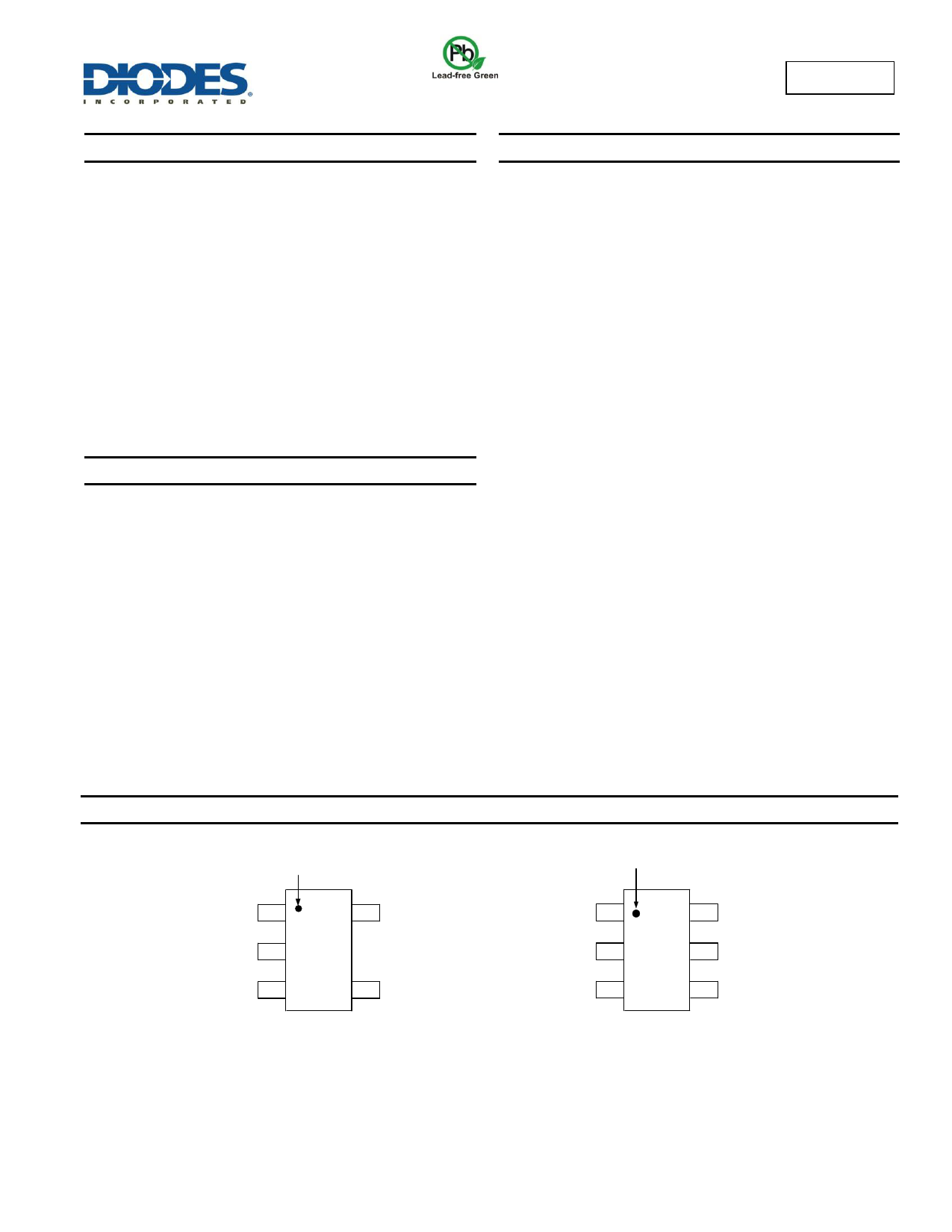
Pin Assignments
(Top View)
Pin 1 Mark
(Top View)
Pin 1 Mark
VM 1
5 CO
DO 1
6 VSS
VDD 2
VM 2
5 VDD
VSS 3
4 DO
CO 3
4 NC
Notes:
SOT25
SOT26
1. No purposely added lead. Fully EU Directive 2002/95/EC (RoHS) & 2011/65/EU (RoHS 2) compliant.
2. See http://www.diodes.com/quality/lead_free.html for more information about Diodes Incorporated’s definitions of Halogen- and Antimony-free, "Green"
and Lead-free.
3. Halogen- and Antimony-free "Green” products are defined as those which contain <900ppm bromine, <900ppm chlorine (<1500ppm total Br + Cl) and
<1000ppm antimony compounds.
AP9101C
Document number: DS37771 Rev. 3 - 2
1 of 18
www.diodes.com
December 2015
© Diodes Incorporated
1 page 
AP9101C
Electrical Characteristics
(TA = +25°C, VDD = 3.5V, VSS = 0V, R1 = 330Ω, R2 = 2.7kΩ, C1 = 100nF, unless otherwise specified.)
Symbol
VCU
VCL
VDL
VDU
VDOC
VSHORT
VCOC
ICC
ISTB
RCOH
RCOL
RDOH
RDOL
RVMD
RVMS
V0CHA
V0INH
VOVCHG
VOVCHGR
tCU
tDL
tDOC
tSHORT
tCOC
Parameter
Test Conditions
Min Typ Max Unit
Overcharge Detection Voltage
Overcharge Release Voltage
Overdischarge Detection Voltage
Overdischarge Release Voltage
Discharge Overcurrent Detection Voltage
Load Short-Circuiting Detection Voltage
Charge Overcurrent Detection Voltage
VCL ≠ VCU
VCL = VCU
VDU ≠ VDL
VDU = VDL
—
—
—
—
—
VCU-0.025
VCU VCU+0.025 V
VCL-0.050
VCL VCL+0.050 V
VCL-0.025
VCL VCL+0.025 V
VDL-0.035
VDL VDL+0.035 V
VDU-0.100
VDU VDU+0.100 V
VDU-0.035
VDU VDU+0.035 V
VDOC-0.015 VDOC VDOC+0.015 V
VSHORT-0.10 VSHORT VSHORT+0.10 V
VCOC-0.015 VCOC VCOC+0.015 V
Current Consumption during Operation
Current Consumption at Power-Down
CO Pin Resistance “H”
VDD = 3.5V, VM = 0V
VDD=1.8V, Power-Down Mode
VM Pin Without Power-Down
Floating Mode (Auto-Wake-up)
VDD = 3.5V, VCO = 3.0V, VM = 0V
CO Pin Resistance “L”
VDD = 4.5V, VCO = 0.5V, VM = 0V
DO Pin Resistance “H”
VDD = 3.5V, VDO = 3.0V, VM = 0V
DO Pin Resistance “L”
VDD = 1.8V, VDO = 0.5V, VM = 0V
Resistance between VM Pin and VDD Pin VDD = 1.8V, VM = 0V
Resistance between VM pin and VSS Pin VDD = 3.5V, VM = 1.0V
0V Battery Charge Starting Charger Voltage 0V Battery Charging “Available”
1.5
—
—
2
2
2
2
150
10
1.2
3 4.5 µA
— 0.1
—
µA
5.5
6 10 kΩ
4 10 kΩ
5 10 kΩ
5 10 kΩ
300 500 kΩ
30 50 kΩ
— —V
0V Battery Charge Inhibition Battery Voltage 0V Battery Charging “Unavailable”
—
— 0.45 V
Overvoltage Charger Detection Voltage
VDD = 3.5V
6.0 8.0 10.0 V
Overvoltage Charger Release Voltage
VDD = 3.5V
Overcharge Detection Delay Time
Overdischarge Detection Delay Time
Discharge Overcurrent Detection Delay
Time
Load Short-Circuiting Detection Delay Time
Charge Overcurrent Detection Delay Time
—
—
—
—
—
5.3
tCU×0.8
tDL×0.7
7.3 9.3 V
tCU
tCU×1.2
ms
tDL
tDL×1.3
ms
tDOC×0.8
tDOC
tDOC×1.2 ms
tSHORT×0.8
tCOC×0.8
tSHORT tSHORT×1.2
tCOC
tCOC×1.2
µs
ms
AP9101C
Document number: DS37771 Rev. 3 - 2
5 of 18
www.diodes.com
December 2015
© Diodes Incorporated
5 Page 
Time Chart (Cont.)
(3) Charge Overcurrent Detection
VDD
VCU
VCL
VDU
VDL
VSS
VDD
DO
VSS
VDD
CO
VM
VDD
VM
VSS
VCOC
VP-
1: tCOC
AP9101C
1
S1
S1: Connect over current charger
AP9101C
Document number: DS37771 Rev. 3 - 2
11 of 18
www.diodes.com
December 2015
© Diodes Incorporated
11 Page | ||
| Páginas | Total 18 Páginas | |
| PDF Descargar | [ Datasheet AP9101C.PDF ] | |
Hoja de datos destacado
| Número de pieza | Descripción | Fabricantes |
| AP9101C | SINGLE CHIP SOLUTION | Diodes |
| Número de pieza | Descripción | Fabricantes |
| SLA6805M | High Voltage 3 phase Motor Driver IC. |
Sanken |
| SDC1742 | 12- and 14-Bit Hybrid Synchro / Resolver-to-Digital Converters. |
Analog Devices |
|
DataSheet.es es una pagina web que funciona como un repositorio de manuales o hoja de datos de muchos de los productos más populares, |
| DataSheet.es | 2020 | Privacy Policy | Contacto | Buscar |