|
|
|
PDF ISL55016 Data sheet ( Hoja de datos )
| Número de pieza | ISL55016 | |
| Descripción | MMIC Silicon Bipolar Differential Amplifier | |
| Fabricantes | Intersil | |
| Logotipo | ||
Hay una vista previa y un enlace de descarga de ISL55016 (archivo pdf) en la parte inferior de esta página. Total 11 Páginas | ||
|
No Preview Available !
®
Data Sheet
June 24, 2008
ISL55016
FN6526.1
MMIC Silicon Bipolar Differential Amplifier
The ISL55016 is a high performance gain block which can
match a 75Ω single-ended source to a 100Ω differential
load. This feature makes the ISL55016 ideal for a wide
range of general-purpose applications such as Satellite TV.
The ISL55016 can be used as single-ended to differential
converter and eliminates the need for an external balun
structure.
Ordering Information
PART
NUMBER
(Note)
TEMP.
PART RANGE PACKAGE
MARKING (°C) (Pb-Free)
PKG.
DWG. #
ISL55016IRTZ-T7* M9
-40 to +85 6 Ld TDFN L6.1.6x1.6B
*Please refer to TB347 for details on reel specifications.
NOTE: These Intersil Pb-free plastic packaged products employ
special Pb-free material sets, molding compounds/die attach
materials, and 100% matte tin plate plus anneal (e3 termination finish,
which is RoHS compliant and compatible with both SnPb and Pb-free
soldering operations). Intersil Pb-free products are MSL classified at
Pb-free peak reflow temperatures that meet or exceed the Pb-free
requirements of IPC/JEDEC J STD-020.
Pinout
ISL55016
(6 LD TDFN)
TOP VIEW
VSM 1
6 VSP
VINM 2 GND 5 VOM
VINP 3
4 VOP
Pin Descriptions
PIN
NUMBER
PIN
NAME
DESCRIPTION
1 VSM Ground
2 VINM Single-Ended Input. VINM should be
AC-Coupled.
3 VINP AC Ground
4, 5 VOP, VOM Differential outputs. VOP and VOM
should be AC-Coupled. Differential
Impedance 100Ω.
6 VSP Power supply. +5V
Features
• Input Impedance of 75Ω Single-Ended
• Output Impedance of 100Ω Differential
• Noise Figure of 5.4dB
• OIP3 of 26dBm
• Input Return Loss of 27dB
• Pb-Free (RoHS Compliant)
Applications
• Active Balun Function
• LNB and LNB-T (HDTV) Amplifiers
• IF Gain Blocks for Satellite and Terrestrial STBs
• PA Driver Amplifier
• Wireless Data, Satellite
• Bluetooth/WiFi
• Satellite Locator and Signal Strength Meters
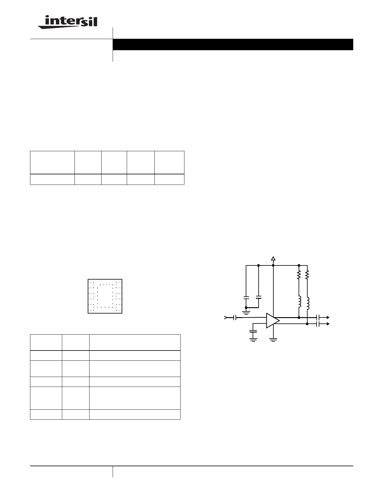
Typical Application Circuit
+5V
27Ω 27Ω
0.1µF
100pF
100pF
100pF
100nH
2 65
3 14
100nH
100pF
100pF
1 CAUTION: These devices are sensitive to electrostatic discharge; follow proper IC Handling Procedures.
1-888-INTERSIL or 1-888-468-3774 | Intersil (and design) is a registered trademark of Intersil Americas Inc.
Copyright © Intersil Americas Inc. 2008. All Rights Reserved.
All other trademarks mentioned are the property of their respective owners.
1 page 
ISL55016
Typical Performance (II)
15
50Ω Environment, ZRSC = 50Ω, ZLOAD Port 2 = 50Ω, ZLOAD Port 3 = 50Ω; Measured on Probe Station.
15
14 14
13 13
12 12
11 11
10
0 0.5G 1.0G 1.5G 2.0G 2.5G 3.0G
FREQUENCY (Hz)
FIGURE 7. |S21| vs FREQUENCY
10
0 0.5G 1.0G 1.5G 2.0G 2.5G 3.0G
FREQUENCY (Hz)
FIGURE 8. |S31| vs FREQUENCY
0
-2
-4
-6
-8
-10
-12
-14
0
0.5G
1.0G 1.5G 2.0G
FREQUENCY (Hz)
2.5G
FIGURE 9. |S11| vs FREQUENCY
3.0G
0
-2
-4
-6
-8
-10
-12
-14
-16
-18
0
0.5G 1.0G 1.5G 2.0G 2.5G
FREQUENCY (Hz)
FIGURE 11. |S22| vs FREQUENCY
3.0G
FIGURE 10. SMITH CHART OF S11
FIGURE 12. SMITH CHART OF S22
5 FN6526.1
June 24, 2008
5 Page 
ISL55016
Package Outline Drawing
L6.1.6x1.6B
6 LEAD THIN DUAL FLAT NO-LEAD PLASTIC PACKAGE (TDFN)
Rev 1, 03/07
6
PIN 1
INDEX AREA
1.60
A
B
0.50BSC
1.00
(4X) 0.15
TOP VIEW
6X 0.25
0.10 M C A B
0.60
R 0.20
6
PIN #1 INDEX AREA
1.00
1.12
BOTTOM VIEW
6X 0.24
(6X 0.6)
1.00
0.60
1.12
TYPICAL RECOMMENDED LAND PATTERN
0.50
0.75
0.000-0.50
SIDE VIEW
SEE DETAIL "X"
0.10 C C
BASE PLANE
SEATING PLANE
0.08 C
( 6 X 0 . 25 )
C
0 . 2 REF
5
0 . 00 MIN.
0 . 05 MAX.
DETAIL "X"
NOTES:
1. Dimensions are in millimeters.
Dimensions in ( ) for Reference Only.
2. Dimensioning and tolerancing conform to AMSEY14.5m-1994.
3. Unless otherwise specified, tolerance : Decimal ± 0.0
4. Dimension b applies to the metallized terminal and is measured
between 0.20mm and 0.30mm from the terminal tip.
5. Tiebar shown (if present) is a non-functional feature.
6. The configuration of the pin #1 identifier is optional, but must be
located within the zone indicated. The pin #1 identifier may be
either a mold or mark feature.
11 FN6526.1
June 24, 2008
11 Page | ||
| Páginas | Total 11 Páginas | |
| PDF Descargar | [ Datasheet ISL55016.PDF ] | |
Hoja de datos destacado
| Número de pieza | Descripción | Fabricantes |
| ISL55010 | MMIC Silicon Bipolar Broadband Amplifier | Intersil Corporation |
| ISL55011 | MMIC Silicon Bipolar Broadband Amplifier | Intersil Corporation |
| ISL55012 | MMIC Silicon Bipolar Broadband Amplifier | Intersil Corporation |
| ISL55013 | MMIC Silicon Bipolar Broadband Amplifier | Intersil Corporation |
| Número de pieza | Descripción | Fabricantes |
| SLA6805M | High Voltage 3 phase Motor Driver IC. |
Sanken |
| SDC1742 | 12- and 14-Bit Hybrid Synchro / Resolver-to-Digital Converters. |
Analog Devices |
|
DataSheet.es es una pagina web que funciona como un repositorio de manuales o hoja de datos de muchos de los productos más populares, |
| DataSheet.es | 2020 | Privacy Policy | Contacto | Buscar |