|
|
|
PDF SIS334DN Data sheet ( Hoja de datos )
| Número de pieza | SIS334DN | |
| Descripción | N-Channel 30V (D-S) MOSFET | |
| Fabricantes | Vishay | |
| Logotipo | ||
Hay una vista previa y un enlace de descarga de SIS334DN (archivo pdf) en la parte inferior de esta página. Total 7 Páginas | ||
|
No Preview Available !
N-Channel 30 V (D-S) MOSFET
SiS334DN
Vishay Siliconix
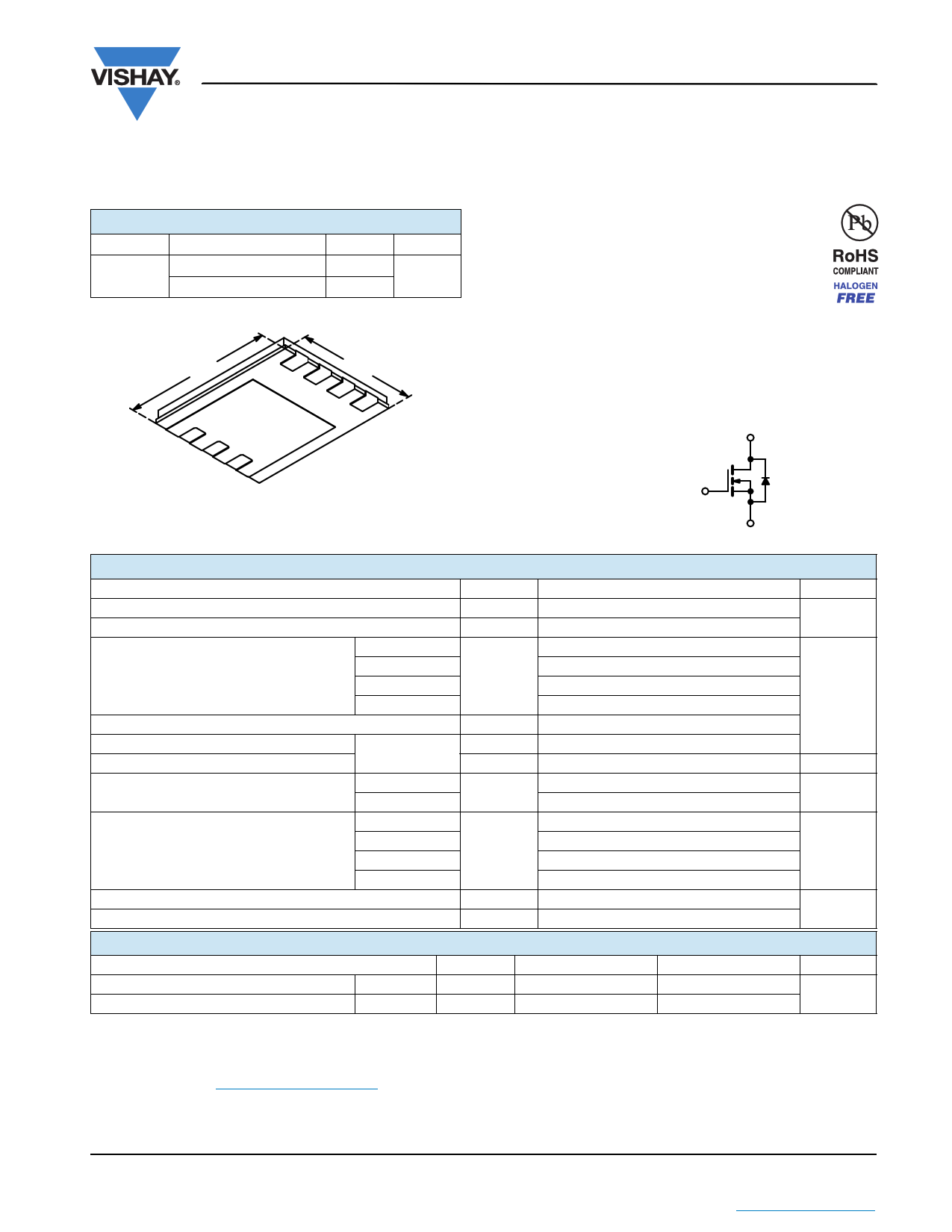
PRODUCT SUMMARY
VDS (V)
30
RDS(on) () Max.
0.0113 at VGS = 10 V
0.0146 at VGS = 4.5 V
ID (A)a
20
20
PowerPAK® 1212-8
Qg (Typ.)
5.1 nC
3.30 mm
D
8D
7
D
6
D
5
S
1S
3.30 mm
2
S
3
G
4
Bottom View
Ordering Information:
SiS334DN-T1-GE3 (Lead (Pb)-free and Halogen-free)
FEATURES
• Halogen-free According to IEC 61249-2-21
Definition
• TrenchFET® Power MOSFET
• 100 % Rg and UIS Tested
• Compliant to RoHS Directive 2002/95/EC
APPLICATIONS
• Notebook/POL
- Synchronous Buck
- High Side
D
G
N-Channel MOSFET
S
ABSOLUTE MAXIMUM RATINGS (TA = 25 °C, unless otherwise noted)
Parameter
Symbol
Drain-Source Voltage
VDS
Gate-Source Voltage
VGS
TC = 25 °C
Continuous Drain Current (TJ = 150 °C)
TC = 70 °C
TA = 25 °C
ID
TA = 70 °C
Pulsed Drain Current (t = 300 µs)
IDM
Avalanche Current
Avalanche Energy
L = 0.1 mH
IAS
EAS
Continuous Source-Drain Diode Current
TC = 25 °C
TA = 25 °C
IS
TC = 25 °C
Maximum Power Dissipation
TC = 70 °C
TA = 25 °C
PD
TA = 70 °C
Operating Junction and Storage Temperature Range
Soldering Recommendations (Peak Temperature)d, e
TJ, Tstg
Limit
30
± 20
20a
20a
13.6b, c
10.8b, c
50
15
11.25
20a
3.4b, c
50
32
3.8b, c
2.4b, c
- 55 to 150
260
Unit
V
A
mJ
A
W
°C
THERMAL RESISTANCE RATINGS
Parameter
Maximum Junction-to-Ambientb, f
Maximum Junction-to-Case (Drain)
t 10 s
Steady State
Symbol
RthJA
RthJC
Typical
27
2
Maximum
33
2.5
Unit
°C/W
Notes:
a. Package limited.
b. Surface mounted on 1" x 1" FR4 board.
c. t = 10 s.
d. See solder profile (www.vishay.com/ppg?73257). The PowerPAK 1212-8 is a leadless package. The end of the lead terminal is exposed
copper (not plated) as a result of the singulation process in manufacturing. A solder fillet at the exposed copper tip cannot be guaranteed
and is not required to ensure adequate bottom side solder interconnection.
e. Rework conditions: manual soldering with a soldering iron is not recommended for leadless components.
f. Maximum under steady state conditions is 81 °C/W.
Document Number: 63371
www.vishay.com
S11-1659-Rev. A, 15-Aug-11
1
This document is subject to change without notice.
THE PRODUCTS DESCRIBED HEREIN AND THIS DOCUMENT ARE SUBJECT TO SPECIFIC DISCLAIMERS, SET FORTH AT www.vishay.com/doc?91000
1 page 
TYPICAL CHARACTERISTICS (25 °C, unless otherwise noted)
60
50
40
30
Limited by Package
20
10
0
0 25 50 75 100 125 150
TC - Case Temperature (°C)
Current Derating*
2.0 65
SiS334DN
Vishay Siliconix
1.6 52
1.2 39
0.8 26
0.4 13
0.0
0
25 50 75 100 125
TA - Ambient Temperature (°C)
Power, Junction-to-Ambient
150
0
0 25 50 75 100 125 150
TC - Case Temperature (°C)
Power, Junction-to-Case
* The power dissipation PD is based on TJ(max) = 150 °C, using junction-to-case thermal resistance, and is more useful in settling the upper
dissipation limit for cases where additional heatsinking is used. It is used to determine the current rating, when this rating falls below the package
limit.
Document Number: 63371
www.vishay.com
S11-1659-Rev. A, 15-Aug-11
5
This document is subject to change without notice.
THE PRODUCTS DESCRIBED HEREIN AND THIS DOCUMENT ARE SUBJECT TO SPECIFIC DISCLAIMERS, SET FORTH AT www.vishay.com/doc?91000
5 Page | ||
| Páginas | Total 7 Páginas | |
| PDF Descargar | [ Datasheet SIS334DN.PDF ] | |
Hoja de datos destacado
| Número de pieza | Descripción | Fabricantes |
| SIS334DN | N-Channel 30V (D-S) MOSFET | Vishay |
| Número de pieza | Descripción | Fabricantes |
| SLA6805M | High Voltage 3 phase Motor Driver IC. |
Sanken |
| SDC1742 | 12- and 14-Bit Hybrid Synchro / Resolver-to-Digital Converters. |
Analog Devices |
|
DataSheet.es es una pagina web que funciona como un repositorio de manuales o hoja de datos de muchos de los productos más populares, |
| DataSheet.es | 2020 | Privacy Policy | Contacto | Buscar |