|
|
|
PDF NE555 Data sheet ( Hoja de datos )
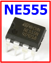
| Número de pieza | NE555 | |
| Descripción | Timers | |
| Fabricantes | Harris Corporation | |
| Logotipo | ||
 1. Bipolar Timer ( PDF ) Hay una vista previa y un enlace de descarga de NE555 (archivo pdf) en la parte inferior de esta página. Total 6 Páginas | ||
|
No Preview Available !
SEMICONDUCTOR
May 1997
CA555, CA555C,
LM555, LM555C, NE555
Timers for Timing Delays and Oscillator Application
in Commercial, Industrial and Military Equipment
Features
• Accurate Timing From Microseconds Through Hours
• Astable and Monostable Operation
• Adjustable Duty Cycle
• Output Capable of Sourcing or Sinking up to 200mA
• Output Capable of Driving TTL Devices
• Normally ON and OFF Outputs
• High Temperature Stability . . . . . . . . . . . . . . 0.005%/oC
• Directly Interchangeable with SE555, NE555, MC1555,
and MC1455
Applications
• Precision Timing
• Pulse Generation
• Sequential Timing
• Pulse Detector
• Time Delay Generation • Pulse Width and Position
Modulation
Ordering Information
PART NUMBER
(BRAND)
TEMP.
RANGE (oC)
PACKAGE
CA0555E
-55 to 125 8 Ld PDIP
CA0555M (555)
-55 to 125 8 Ld SOIC
CA0555M96 (555)
-55 to 125 8 Ld SOIC †
CA0555T
-55 to 125 8 Pin Metal Can
CA0555CE
0 to 70 8 Ld PDIP
CA0555CM (555C)
0 to 70 8 Ld SOIC
CA0555CM96 (555C)
0 to 70 8 Ld SOIC †
CA0555CT
0 to 70 8 Pin Metal Can
LM555N
-55 to 125 8 Ld PDIP
LM555CN
0 to 70 8 Ld PDIP
NE555N
0 to 70 8 Ld PDIP
NOTE: † Denotes Tape and Reel
PKG.
NO.
E8.3
M8.15
M8.15
T8.C
E8.3
M8.15
M8.15
T8.C
E8.3
E8.3
E8.3
Description
The CA555 and CA555C are highly stable timers for use in
precision timing and oscillator applications. As timers, these
monolithic integrated circuits are capable of producing accu-
rate time delays for periods ranging from microseconds
through hours. These devices are also useful for astable
oscillator operation and can maintain an accurately con-
trolled free running frequency and duty cycle with only two
external resistors and one capacitor.
The circuits of the CA555 and CA555C may be triggered by
the falling edge of the waveform signal, and the output of
these circuits can source or sink up to a 200mA current or
drive TTL circuits.
These types are direct replacements for industry types in
packages with similar terminal arrangements e.g. SE555
and NE555, MC1555 and MC1455, respectively. The CA555
type circuits are intended for applications requiring premium
electrical performance. The CA555C type circuits are
intended for applications requiring less stringent electrical
characteristics.
Pinouts
CA555, CA555C (PDIP, SOIC)
LM555, LM555C, NE555 (PDIP)
TOP VIEW
GND 1
8 V+
TRIGGER 2
7 DISCHARGE
OUTPUT 3
6 THRESHOLD
RESET 4
5 CONTROL
VOLTAGE
CA555, CA555C (METAL CAN)
TOP VIEW
GND 1
V+
8
TAB
7 DISCHARGE
TRIGGER 2
6 THRESHOLD
OUTPUT 3
5 CONTROL
4 VOLTAGE
RESET
Functional Block Diagram
V+ TRIGGER
CONTROL
8 VOLTAGE 5 2
6
THRESHOLD
COMPAR
4
TRIGGER
COMPAR
FLIP-FLOP
3
OUTPUT
7
1
GND
CAUTION: These devices are sensitive to electrostatic discharge. Users should follow proper IC Handling Procedures.
Copyright © Harris Corporation 1997
8-3
File Number 834.4
1 page 
CA555, CA555C, LM555, LM555C, NE555
t1 t2
5V
0
3.3V
100
TA = 25oC, V+ = 5V
10
R1 + 2R2 = 1kΩ
1 10kΩ
100kΩ
1MΩ
0.1 10MΩ
1.7V
0
Top Trace: Output voltage (2V/Div. and 0.5ms/Div.)
Bottom Trace: Capacitor voltage (1V/Div. and 0.5ms/Div.)
FIGURE 5. TYPICAL WAVEFORMS FOR REPEAT CYCLE TIMER
Typical Performance Curves
0.01
0.001
10-1
1
10 102 103 104 105
FREQUENCY (Hz)
FIGURE 6. FREE RUNNING FREQUENCY OF REPEAT CYCLE
TIMER WITH VARIATION IN CAPACITANCE AND
RESISTANCE
150
100 TA = -55oC
0oC
25oC
50 70oC
125oC
0 0.1 0.2 0.3 0.4
MINIMUM TRIGGER (PULSE) VOLTAGE (x V+) (NOTE)
NOTE: Where x is the decimal multiplier of the supply voltage.
FIGURE 7. MINIMUM PULSE WIDTH vs MINIMUM TRIGGER
VOLTAGE
2.0
TA = -55oC
1.6
25oC
1.2
125oC
0.8
0.4
5V ≤ V+ ≤ 15V
0
1 10
SOURCE CURRENT (mA)
FIGURE 9. OUTPUT VOLTAGE DROP (HIGH STATE) vs
SOURCE CURRENT
100
10 TA = 125oC
9
8 25oC
7
6 50oC
5
4
3
2
1
0 2.5
5 7.5 10 12.5
SUPPLY VOLTAGE (V)
15
FIGURE 8. SUPPLY CURRENT vs SUPPLY VOLTAGE
10.0
V+ = 5V
1.0
TA = -55oC
25oC
125oC
0.1
0.01
1
10
SINK CURRENT (mA)
FIGURE 10. OUTPUT VOLTAGE LOW STATE vs SINK
CURRENT
100
8-7
5 Page | ||

| Páginas | Total 6 Páginas | |
| PDF Descargar | [ Datasheet NE555.PDF ] | |
Hoja de datos destacado
| Número de pieza | Descripción | Fabricantes |
| NE5500179A | SILICON POWER MOS FET | NEC |
| NE5500179A-T1 | SILICON POWER MOS FET | NEC |
| NE5510179A | 3.5V OPERATION SILICON RF POWER MOSFET | NEC |
| NE5510279A | 3.5V OPERATION SILICON RF POWER MOSFET | NEC |
| Número de pieza | Descripción | Fabricantes |
| SLA6805M | High Voltage 3 phase Motor Driver IC. |
Sanken |
| SDC1742 | 12- and 14-Bit Hybrid Synchro / Resolver-to-Digital Converters. |
Analog Devices |
|
DataSheet.es es una pagina web que funciona como un repositorio de manuales o hoja de datos de muchos de los productos más populares, |
| DataSheet.es | 2020 | Privacy Policy | Contacto | Buscar |