|
|
|
PDF 54HC589A Data sheet ( Hoja de datos )
| Número de pieza | 54HC589A | |
| Descripción | 8-Bit Serial or Parallel-Input/Serial-Output Shift Register | |
| Fabricantes | Motorola Semiconductors | |
| Logotipo | ||
Hay una vista previa y un enlace de descarga de 54HC589A (archivo pdf) en la parte inferior de esta página. Total 11 Páginas | ||
|
No Preview Available !
MOTOROLA
SEMICONDUCTOR TECHNICAL DATA
Product Preview
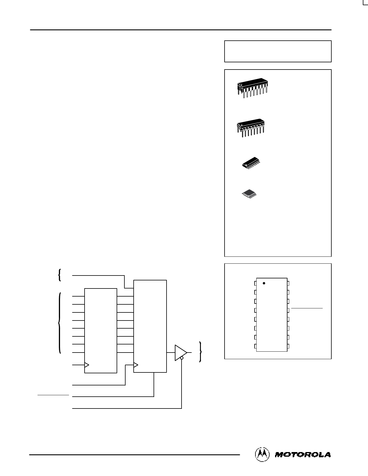
8-Bit Serial or Parallel-Input/
Serial-Output Shift Register
with 3-State Output
High–Performance Silicon–Gate CMOS
The MC54/74HC589A is similar in function to the HC597, which is not a
3–state device. The device inputs are compatible with standard CMOS
outputs, with pullup resistors, they are compatible with LSTTL outputs.
This device consists of an 8–bit storage latch which feeds parallel data to
an 8–bit shift register. Data can also be loaded serially (see Function Table).
The shift register output, QH, is a three–state output, allowing this device to
be used in bus–oriented systems.
The HC589A directly interfaces with the Motorola SPI serial data port on
CMOS MPUs and MCUs.
• Output Drive Capability: 15 LSTTL Loads
• Outputs Directly Interface to CMOS, NMOS, and TTL
• Operating Voltage Range: 2 to 6 V
• Low Input Current: 1 µA
• High Noise Immunity Characteristic of CMOS Devices
• In Compliance with the Requirements Defined by JEDEC Standard
No. 7A
• Chip Complexity: 526 FETs or 131.5 Equivalent Gates
SERIAL
DATA
INPUT
SA 14
PARALLEL
DATA
INPUTS
A 15
B1
C2
D3
E4
F5
G6
H7
LATCH CLOCK 12
LOGIC DIAGRAM
DATA
LATCH
SHIFT
REGISTER
VCC = PIN 16
GND = PIN 8
SERIAL
9 QH DATA
OUTPUT
MC54/74HC589A
16
1
J SUFFIX
CERAMIC PACKAGE
CASE 620–10
16
1
N SUFFIX
PLASTIC PACKAGE
CASE 648–08
16
1
16
1
D SUFFIX
SOIC PACKAGE
CASE 751B–05
DT SUFFIX
TSSOP PACKAGE
CASE 948F–01
ORDERING INFORMATION
MC54HCXXXAJ
MC74HCXXXAN
MC74HCXXXAD
MC74HCXXXADT
Ceramic
Plastic
SOIC
TSSOP
PIN ASSIGNMENT
B1
C2
16 VCC
15 A
D3
E4
F5
14 SA
13
SERIAL SHIFT/
PARALLEL LOAD
12 LATCH CLOCK
G6
H7
11 SHIFT CLOCK
10 OUTPUT ENABLE
GND 8
9 QH
SHIFT CLOCK 11
SERIAL SHIFT/
PARALLEL LOAD
OUTPUT ENABLE
13
10
This document contains information on a product under development. Motorola reserves the right to change or discontinue this product without notice.
10/95
© Motorola, Inc. 1995
1 REV 0
1 page 
MC54/74HC589A
FUNCTION TABLE
Inputs
Resulting Function
Operation
Output Serial Shift/ Latch
Enable Parallel Load Clock
Force output into high
H
X
X
impedance state
Load parallel data into
data latch
L
H
Transfer latch contents to
shift register
L
L L, H,
Contents of input latch
and shift register are
unchanged
L
H L, H,
Load parallel data into
data latch and shift
register
L
L
Shift serial data into shift
L
H
X
register
Load parallel data in data
latch and shift serial data
into shift register
L
H
LR = latch register contents
SR = shift register contents
a–h = data at parallel data inputs A–H
D = data (L, H) at serial data input SA
Shift
Clock
X
Serial
Input
SA
X
Parallel
Inputs
A–H
X
Data
Latch
Contents
X
Shift
Register
Contents
X
L, H,
X a–h
a–h
U
X
L, H,
X
X
X
X
U LRN → SRN
UU
Output
QH
Z
U
LRH
U
X X a–h a–h
a–h
h
DX
D a–h
*
SRA = D,
SRG → SRH
SRN → SRN+1
a–h
SRA = D,
SRG → SRH
SRN → SRN+1
U = remains unchanged
X = don’t care
Z = high impedance
* = depends on Latch Clock input
High–Speed CMOS Logic Data
DL129 — Rev 6
5
MOTOROLA
5 Page 
MC54/74HC589A
OUTLINE DIMENSIONS
0.15 (0.006) T U S
16
2X L/2
L
PIN 1
IDENT.
1
0.15 (0.006) T U S
0.10 (0.004)
–T– SEATING
PLANE
D
C
DT SUFFIX
PLASTIC TSSOP PACKAGE
CASE 948F–01
ISSUE O
16X K REF
0.10 (0.004) M
9
8
A
–V–
G
T U S VS
J1
ÇÇÇÇÉÉÉÉKKÇÇÇÇÉÉÉÉ1
NOTES:
1. DIMENSIONING AND TOLERANCING PER ANSI
Y14.5M, 1982.
2. CONTROLLING DIMENSION: MILLIMETER.
3. DIMENSION A DOES NOT INCLUDE MOLD FLASH.
PROTRUSIONS OR GATE BURRS. MOLD FLASH OR
GATE BURRS SHALL NOT EXCEED 0.15 (0.006) PER
SIDE.
4. DIMENSION B DOES NOT INCLUDE INTERLEAD
B
–U– J
SECTION N–N
FLASH OR PROTRUSION. INTERLEAD FLASH OR
PROTRUSION SHALL NOT EXCEED
0.25 (0.010) PER SIDE.
5. DIMENSION K DOES NOT INCLUDE DAMBAR
PROTRUSION. ALLOWABLE DAMBAR PROTRUSION
SHALL BE 0.08 (0.003) TOTAL IN EXCESS OF THE K
DIMENSION AT MAXIMUM MATERIAL CONDITION.
N
0.25 (0.010)
6. TERMINAL NUMBERS ARE SHOWN FOR
REFERENCE ONLY.
7. DIMENSION A AND B ARE TO BE DETERMINED AT
DATUM PLANE –W–.
M
MILLIMETERS
INCHES
DIM MIN MAX MIN MAX
N A 4.90 5.10 0.193 0.200
B 4.30 4.50 0.169 0.177
F C ––– 1.20 ––– 0.047
D 0.05 0.15 0.002 0.006
DETAIL E
F 0.50 0.75 0.020 0.030
G 0.65 BSC
0.026 BSC
H 0.18 0.28 0.007 0.011
J 0.09 0.20 0.004 0.008
–W–
J1 0.09 0.16 0.004 0.006
K 0.19 0.30 0.007 0.012
K1 0.19 0.25 0.007 0.010
H DETAIL E
L 6.40 BSC
0.252 BSC
M 0_ 8_ 0_ 8_
Motorola reserves the right to make changes without further notice to any products herein. Motorola makes no warranty, representation or guarantee regarding
the suitability of its products for any particular purpose, nor does Motorola assume any liability arising out of the application or use of any product or circuit,
and specifically disclaims any and all liability, including without limitation consequential or incidental damages. “Typical” parameters can and do vary in different
applications. All operating parameters, including “Typicals” must be validated for each customer application by customer’s technical experts. Motorola does
not convey any license under its patent rights nor the rights of others. Motorola products are not designed, intended, or authorized for use as components in
systems intended for surgical implant into the body, or other applications intended to support or sustain life, or for any other application in which the failure of
the Motorola product could create a situation where personal injury or death may occur. Should Buyer purchase or use Motorola products for any such
unintended or unauthorized application, Buyer shall indemnify and hold Motorola and its officers, employees, subsidiaries, affiliates, and distributors harmless
against all claims, costs, damages, and expenses, and reasonable attorney fees arising out of, directly or indirectly, any claim of personal injury or death
associated with such unintended or unauthorized use, even if such claim alleges that Motorola was negligent regarding the design or manufacture of the part.
Motorola and are registered trademarks of Motorola, Inc. Motorola, Inc. is an Equal Opportunity/Affirmative Action Employer.
How to reach us:
USA/EUROPE: Motorola Literature Distribution;
P.O. Box 20912; Phoenix, Arizona 85036. 1–800–441–2447
JAPAN: Nippon Motorola Ltd.; Tatsumi–SPD–JLDC, Toshikatsu Otsuki,
6F Seibu–Butsuryu–Center, 3–14–2 Tatsumi Koto–Ku, Tokyo 135, Japan. 03–3521–8315
MFAX: [email protected] –TOUCHTONE (602) 244–6609
INTERNET: http://Design–NET.com
HONG KONG: Motorola Semiconductors H.K. Ltd.; 8B Tai Ping Industrial Park,
51 Ting Kok Road, Tai Po, N.T., Hong Kong. 852–26629298
High–Speed CMOS Logic Data
DL129 — Rev 6
◊ CODELINE
*MC54/74HC58A9/D*MC54/74HC58A9/D
11 MOTOROLA
11 Page | ||
| Páginas | Total 11 Páginas | |
| PDF Descargar | [ Datasheet 54HC589A.PDF ] | |
Hoja de datos destacado
| Número de pieza | Descripción | Fabricantes |
| 54HC589 | 8-Bit Serial or Parallel-Input/Serial-Output Shift Register | Motorola Semiconductors |
| 54HC589A | 8-Bit Serial or Parallel-Input/Serial-Output Shift Register | Motorola Semiconductors |
| Número de pieza | Descripción | Fabricantes |
| SLA6805M | High Voltage 3 phase Motor Driver IC. |
Sanken |
| SDC1742 | 12- and 14-Bit Hybrid Synchro / Resolver-to-Digital Converters. |
Analog Devices |
|
DataSheet.es es una pagina web que funciona como un repositorio de manuales o hoja de datos de muchos de los productos más populares, |
| DataSheet.es | 2020 | Privacy Policy | Contacto | Buscar |