|
|
|
PDF HCPL-2612 Data sheet ( Hoja de datos )
| Número de pieza | HCPL-2612 | |
| Descripción | High CMR Line Receiver Optocouplers | |
| Fabricantes | Avago | |
| Logotipo | ||
Hay una vista previa y un enlace de descarga de HCPL-2612 (archivo pdf) en la parte inferior de esta página. Total 16 Páginas | ||
|
No Preview Available !
HCPL-2602/2612
High CMR Line Receiver Optocouplers
Data Sheet
Description
The HCPL-2602/12 are optically coupled line receivers
that combine a GaAsP light emitting diode, an input
current regulator and an integrated high gain photo
detector. The input regulator serves as a line
termination for line receiver applications. It clamps
the line voltage and regulates the LED current so line
reflections do not interfere with circuit performance.
The regulator allows a typical LED current of 8.5 mA
before it starts to shunt excess current. The output
of the detector IC is an open collector Schottky clamped
transistor. An enable input gates the detector. The
internal detector shield provides a guaranteed
common mode transient immunity specification of
1000 V/ms for the 2602, and 3500 V/ms for the 2612.
DC specifications are defined similar to TTL logic.
The optocoupler ac and dc operational parameters
are guaranteed from 0°C to 70°C allowing trouble-
free interfacing with digital logic circuits. An input
current of 5 mA will sink an eight gate fan-out (TTL)
at the output.
The HCPL-2602/12 are useful as line receivers in
high noise environments that conventional line
receivers cannot tolerate. The higher LED threshold
voltage provides improved immunity to differential
noise and the internally shielded detector provides
orders of magnitude improvement in common mode
rejection with little or no sacrifice in speed.
Features
• 1000 V/µs minimum Common Mode Rejection (CMR) at
VCM = 50 V for HCPL-2602 and 3.5 kV/µs minimum
CMR at VCM = 300 V for HCPL-2612
• Line termination included – no extra circuitry required
• Accepts a broad range of drive conditions
• LED protection minimizes LED efficiency degradation
• High speed: 10 MBd (limited by transmission line in
many applications)
• Guaranteed AC and DC performance over temperature:
0°C to 70°C
• External base lead allows “LED peaking” and LED
current adjustment
• Safety approval
UL recognized – 3750 V rms for 1 Minute
CSA approved
• MIL-PRF-38534 hermetic version available (HCPL-1930/1)
Applications
• Isolated line receiver
• Computer-peripheral interface
• Microprocessor system interface
• Digital isolation for A/D, D/A conversion
• Current sensing
• Instrument input/output isolation
• Ground loop elimination
• Pulse transformer replacement
• Power transistor isolation in motor drives
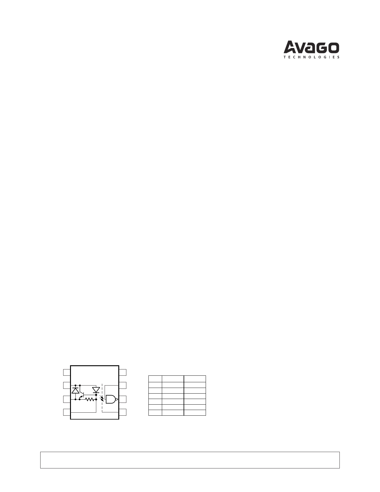
Functional Diagram
NC 1
IN+ 2
IN– 3
CATHODE 4
SHIELD
8 VCC
7 VE
6 VO
5 GND
TRUTH TABLE
(POSITIVE LOGIC)
LED
ON
OFF
ON
OFF
ON
OFF
ENABLE
H
H
L
L
NC
NC
OUTPUT
L
H
H
H
L
H
A 0.1 µF bypass capacitor must be connected between pins 5 and 8.
CAUTION: It is advised that normal static precautions be taken in handling and assembly of this component to
prevent damage and/or degradation which may be induced by ESD.
1 page 
Solder Reflow Thermal Profile
300
PREHEATING RATE 3°C + 1°C/–0.5°C/SEC.
REFLOW HEATING RATE 2.5°C ± 0.5°C/SEC. PEAK
TEMP.
245°C
200
160°C
150°C
140°C
100
2.5°C ± 0.5°C/SEC.
3°C + 1°C/–0.5°C
PREHEATING TIME
150°C, 90 + 30 SEC.
30
SEC.
30
SEC.
PEAK
TEMP.
240°C
PEAK
TEMP.
230°C
SOLDERING
TIME
200°C
50 SEC.
ROOM
TEMPERATURE
0
0
TIGHT
TYPICAL
LOOSE
50 100 150 200 250
TIME (SECONDS)
Regulatory Information
The HCPL-2602/2612 have been
approved by the following
organizations:
UL
Recognized under UL 1577,
Component Recognition Program,
File E55361.
CSA
Approved under CSA Component
Acceptance Notice #5, File CA
88324.
Recommended Pb-Free IR Profile
Tp 260 +0/-5 °C
TL 217 °C
RAMP-UP
3 °C/SEC. MAX.
Tsmax 150 - 200 °C
Tsmin
ts
PREHEAT
60 to 180 SEC.
tp
tL
TIME WITHIN 5 °C of ACTUAL
PEAK TEMPERATURE
20-40 SEC.
RAMP-DOWN
6 °C/SEC. MAX.
60 to 150 SEC.
25
t 25 °C to PEAK
TIME
NOTES:
THE TIME FROM 25 °C to PEAK TEMPERATURE = 8 MINUTES MAX.
Tsmax = 200 °C, Tsmin = 150 °C
Insulation and Safety Related Specifications
Parameter
Symbol Value
Min. External Air Gap
(External Clearance)
L(I01)
7.1
Min. External Tracking
Path (External Creepage)
L(I02)
7.4
Min. Internal Plastic
Gap (Internal Clearance)
0.08
Tracking Resistance
(Comparative Tracking
Index)
Isolation Group
CTI 200
IIIa
Units
mm
mm
mm
V
Conditions
Measured from input terminals to output terminals,
shortest distance through air.
Measured from input terminals to output terminals,
shortest distance path along body.
Through insulation distance, conductor to conductor,
usually the direct distance between the photoemitter
and photodetector inside the optocoupler cavity.
DIN IEC 112/VDE 0303 Part 1
Material Group (DIN VDE 0110, 1/89, Table 1)
Option 300 - surface mount classification is Class A in accordance with CECC 00802.
5
5 Page 
VCC = 5 V
II = 7.5 mA
tRISE
tFALL
300 RL = 4 kΩ
290
60
RL = 1 kΩ
40
20 RL = 350 Ω
0 RL = 350 Ω, 1 kΩ, 4 kΩ
-60 -40 -20 0 20 40 60 80 100
TA – TEMPERATURE – °C
Figure 12. Typical rise and fall time vs.
temperature.
II
B
A
1
2
3
VCC 8
7
6
+5 V
0.1 µF
BYPASS
350 Ω
OUTPUT VO
MONITORING
NODE
4 GND 5
VCM
+–
PULSE
GENERATOR
ZO = 50 Ω
VCM (PEAK)
VCM
0V
5 V SWITCH AT A: II = 0 mA
VO VO (MIN.)
SWITCH AT B: II = 7.5 mA
VO 0.5 V
VO (MAX.)
CMH
CML
Figure 13. Test circuit for common mode transient immunity and typical waveforms.
5
VCC = 5.0 V
VO = 0.6 V
4
3
RL = 350 Ω
2
RL = 1 kΩ
1 RL = 4 kΩ
0
-60 -40 -20 0 20 40 60 80 100
TA – TEMPERATURE – °C
Figure 14. Typical input threshold current vs.
temperature.
VCC BUS (FRONT)
NC
NC
NC
NC
GND BUS (BACK)
0.1µF
0.1µF
ENABLE
(IF USED)
OUTPUT 1
ENABLE
(IF USED)
OUTPUT 2
10 mm MAX.
(SEE NOTE 1)
Figure 15. Recommended printed circuit board layout.
11
11 Page | ||
| Páginas | Total 16 Páginas | |
| PDF Descargar | [ Datasheet HCPL-2612.PDF ] | |
Hoja de datos destacado
| Número de pieza | Descripción | Fabricantes |
| HCPL-2611 | High Speed TTL Compatible Optocouplers | HP |
| HCPL-2611 | HIGH SPEED-10 MBit/s LOGIC GATE OPTOCOUPLERS | Fairchild Semiconductor |
| HCPL-2611 | HIGH SPEED-10 MBit/s LOGIC GATE OPTOCOUPLERS | QT Optoelectronics |
| HCPL-2611 | High Speed TTL Compatible Optocouplers | Avago |
| Número de pieza | Descripción | Fabricantes |
| SLA6805M | High Voltage 3 phase Motor Driver IC. |
Sanken |
| SDC1742 | 12- and 14-Bit Hybrid Synchro / Resolver-to-Digital Converters. |
Analog Devices |
|
DataSheet.es es una pagina web que funciona como un repositorio de manuales o hoja de datos de muchos de los productos más populares, |
| DataSheet.es | 2020 | Privacy Policy | Contacto | Buscar |