|
|
|
PDF GA100TS120U Data sheet ( Hoja de datos )
| Número de pieza | GA100TS120U | |
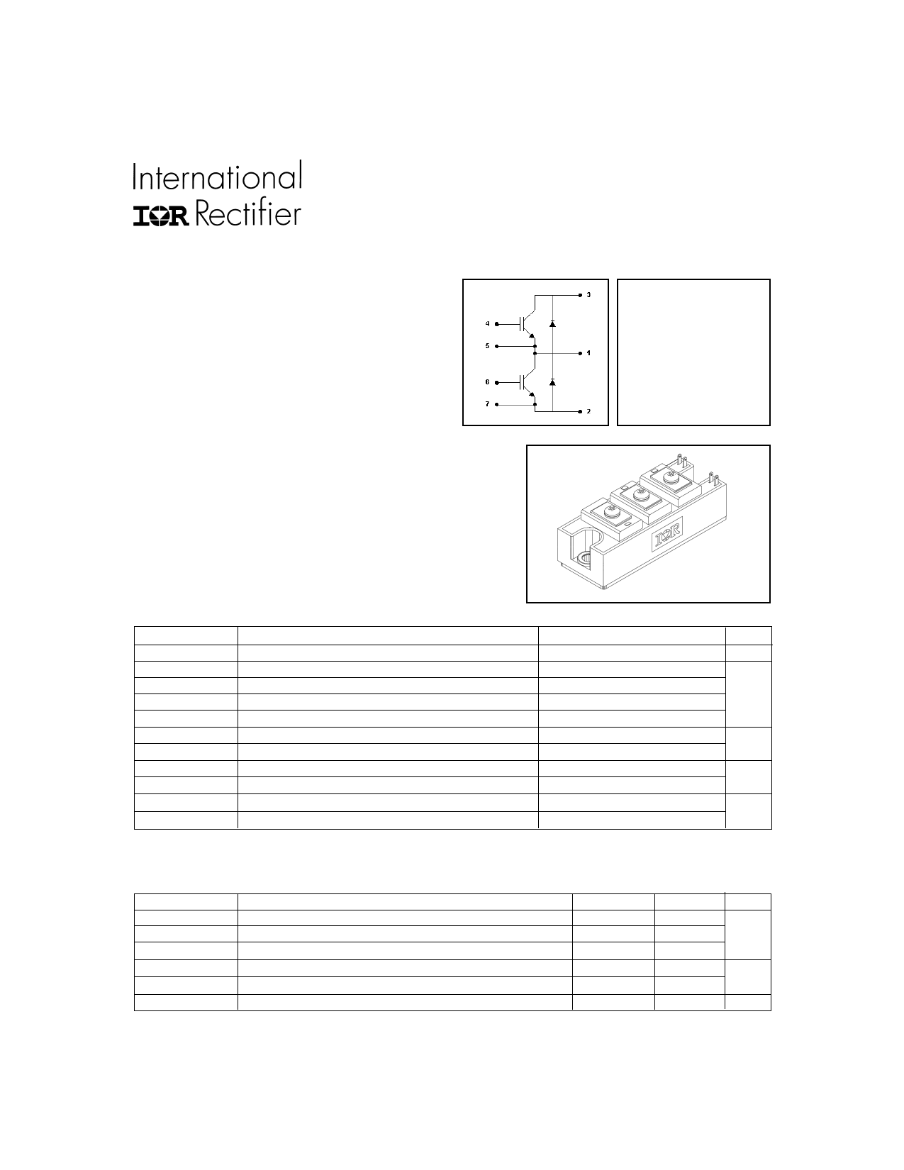
| Descripción | HALF-BRIDGE IGBT INT-A-PAK | |
| Fabricantes | International Rectifier | |
| Logotipo | ||
Hay una vista previa y un enlace de descarga de GA100TS120U (archivo pdf) en la parte inferior de esta página. Total 10 Páginas | ||
|
No Preview Available !
"HALF-BRIDGE" IGBT INT-A-PAK
Features
• Generation 4 IGBT technology
• UltraFast: Optimized for high operating
frequencies 8-40 kHz in hard switching, >200
kHz in resonant mode
• Very low conduction and switching losses
• HEXFRED™ antiparallel diodes with ultra- soft
recovery
• Industry standard package
• UL approved
Benefits
• Increased operating efficiency
• Direct mounting to heatsink
• Performance optimized for power conversion: UPS,
SMPS, Welding
• Lower EMI, requires less snubbing
PD - 50060B
GA100TS120U
Ultra-FastTM Speed IGBT
VCES = 1200V
VCE(on) typ. = 2.4V
@VGE = 15V, IC = 100A
Absolute Maximum Ratings
VCES
IC @ TC = 25°C
ICM
ILM
IFM
VGE
VISOL
PD @ TC = 25°C
PD @ TC = 85°C
TJ
TSTG
Parameter
Collector-to-Emitter Voltage
Continuous Collector Current
Pulsed Collector Current ➀
Peak Switching Current ➁
Peak Diode Forward Current
Gate-to-Emitter Voltage
RMS Isolation Voltage, Any Terminal To Case, t = 1 min
Maximum Power Dissipation
Maximum Power Dissipation
Operating Junction Temperature Range
Storage Temperature Range
Max.
1200
100
200
200
200
±20
2500
520
270
-40 to +150
-40 to +125
Units
V
A
V
W
°C
Thermal / Mechanical Characteristics
RθJC
RθJC
RθCS
www.irf.com
Parameter
Thermal Resistance, Junction-to-Case - IGBT
Thermal Resistance, Junction-to-Case - Diode
Thermal Resistance, Case-to-Sink - Module
Mounting Torque, Case-to-Heatsink
Mounting Torque, Case-to-Terminal 1, 2 & 3 ➂
Weight of Module
Typ.
—
—
0.1
—
—
200
Max.
0.24
0.35
—
4.0
3.0
—
Units
°C/W
N.m
g
1
4/24/2000
1 page 
GA100TS120U
35000
28000
21000
VGE = 0V, f = 1MHz
Cies = Cge + Cgc , Cce
Cres = Cgc
Coes = Cce + Cgc
SHORTED
Cies
14000
7000
Coes
Cres
0
1 10 100
VCE , Collector-to-Emitter Voltage (V)
20
VCC = 400V
I C = 113A
16
12
8
4
0
0 300 600 900
QG , Total Gate Charge (nC)
Fig. 7 - Typical Capacitance vs.
Collector-to-Emitter Voltage
Fig. 8 - Typical Gate Charge vs.
Gate-to-Emitter Voltage
60
VCC = 720V
VGE = 15V
TJ = 125 °C
IC = 100A
50
40
1000 RGG1=1=5OΩh;RmG2 = 0 Ω
VGE = 15V
VCC = 720V
100
10
IC = 200 A
IC = 100 A
IC = 50 A
30
10
20 30 40
RG , Gate Resistance (Ohm)
50
Fig. 9 - Typical Switching Losses vs. Gate
Resistance
www.irf.com
1
-60 -40 -20 0 20 40 60 80 100 120 140 160
TJ , Junction Temperature °( C )
Fig. 10 - Typical Switching Losses vs.
Junction Temperature
5
5 Page | ||
| Páginas | Total 10 Páginas | |
| PDF Descargar | [ Datasheet GA100TS120U.PDF ] | |
Hoja de datos destacado
| Número de pieza | Descripción | Fabricantes |
| GA100TS120U | HALF-BRIDGE IGBT INT-A-PAK | International Rectifier |
| GA100TS120UPBF | IGBT | Vishay Siliconix |
| Número de pieza | Descripción | Fabricantes |
| SLA6805M | High Voltage 3 phase Motor Driver IC. |
Sanken |
| SDC1742 | 12- and 14-Bit Hybrid Synchro / Resolver-to-Digital Converters. |
Analog Devices |
|
DataSheet.es es una pagina web que funciona como un repositorio de manuales o hoja de datos de muchos de los productos más populares, |
| DataSheet.es | 2020 | Privacy Policy | Contacto | Buscar |