|
|
|
PDF MP3418 Data sheet ( Hoja de datos )
| Número de pieza | MP3418 | |
| Descripción | 400mA 1.2MHz Synchronous Step-up Converter | |
| Fabricantes | MPS | |
| Logotipo | ||
Hay una vista previa y un enlace de descarga de MP3418 (archivo pdf) en la parte inferior de esta página. Total 14 Páginas | ||
|
No Preview Available !
The Future of Analog IC Technology
MP3418
400mA, 1.2MHz, Synchronous, Step-up
Converter with Output Disconnect
DESCRIPTION
The MP3418 is a high-efficiency, synchronous,
current–mode, step-up converter with output
disconnect.
The MP3418 can start up from an input voltage
as low as 0.8V to provide inrush current limiting,
and output short-circuit protection. The
integrated, P-channel, synchronous rectifier
improves efficiency and eliminates the need for
an external Schottky diode. The PMOS
disconnects the output from the input when the
part shuts down. This output disconnect feature
allows the output to be completely discharged,
thus allowing the part to draw less than 1µA in
shutdown mode.
The 1.2MHz switching frequency allows for
smaller external components, while the internal
compensation and the soft-start minimize the
external component count: these feature help to
produce a compact solution for a wide current
load range.
The MP3418 is available in a small 8-pin
TSOT23 package.
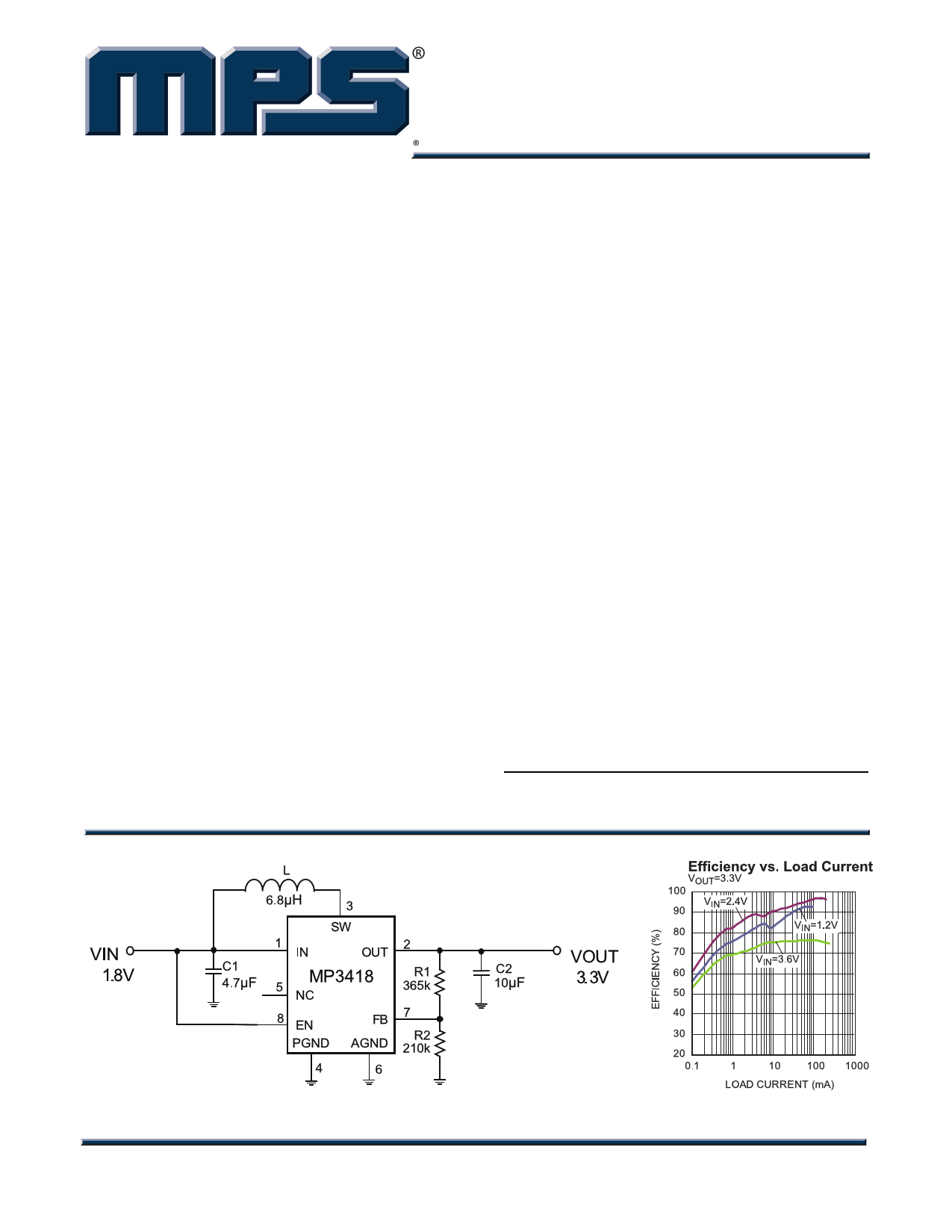
TYPICAL APPLICATION CIRCUIT
FEATURES
• Up to 96% Efficiency
• 0.8V Low Voltage Start-Up
• 0.6V-to-4V Input Range
• 1.8V-to-4V Output Range
• Internal Synchronous Rectifier
• 1.2MHz Fixed-Frequency Switching
• Typical 38µA Quiescent Current
• Typical 0.1µA Shutdown Current
• Current-Mode Control with Internal
Compensation
• True Output Disconnect from Input
• VIN>VOUT Down Mode Operation
• High Efficiency under Light-Load Conditions
• Very Small External Components
• Inrush Current Limiting and Internal Soft-
Start
• Over-Voltage Protection
• Short-Circuit Protection
• TSOT23-8 Package
APPLICATIONS
• Battery-Powered Products
• Personal Medical Devices
• Portable Media Players
• Wireless Peripherals
• Handheld Computers and Smartphones
All MPS parts are lead-free and adhere to the RoHS directive. For MPS green
status, please visit MPS website under Quality Assurance. “MPS” and “The
Future of Analog IC Technology” are Registered Trademarks of Monolithic
Power Systems, Inc.
MP3418 Rev 1.0
2/7/2013
www.MonolithicPower.com
MPS Proprietary Information. Patent Protected. Unauthorized Photocopy and Duplication Prohibited.
© 2013 MPS. All Rights Reserved.
1
1 page 
MP3418 – 400mA, 1.2MHz, SYNCHRONOUS, STEP-UP CONVERTER WITH OUTPUT DISCONNECT
TYPICAL PERFORMANCE CHARACTERISTICS (continued)
Performance waveforms are tested on the evaluation board in the Design Example section.
VIN = 2.4V, VOUT = 3.3V, L = 6.8µH, COUT=10uF, TA = 25°C, unless otherwise noted.
MP3418 Rev 1.0
2/7/2013
www.MonolithicPower.com
MPS Proprietary Information. Patent Protected. Unauthorized Photocopy and Duplication Prohibited.
© 2013 MPS. All Rights Reserved.
5
5 Page 
MP3418 – 400mA, 1.2MHz, SYNCHRONOUS, STEP-UP CONVERTER WITH OUTPUT DISCONNECT
APPLICATION INFORMATION
COMPONENT SELECTION
Input Capacitor Selection
Low ESR input capacitors reduce input
switching noise and reduce the peak current
drawn from the battery. It follows that ceramic
capacitors are also a good choice for input
decoupling and should be located as close as
possible to the device. Add a ceramic capacitor
larger than 4.7µF in parallel with a 100nF
ceramic capacitor close to the IC.
Output Capacitor Selection
The output capacitor requires a minimum
capacitance value of 10µF at the programmed
output voltage to ensure stability over the full
operating range. A higher capacitance value
may be required to lower the output ripple and
also the transient response. Low ESR
capacitors, such as X5R- or X7R-type ceramic
capacitors, are recommended. Assuming that
the ESR is zero, estimate the minimum output
capacitance to support the ripple in the PWM
mode as.
CO
≥
IO
× (VOUT(MAX) − VIN(MIN) )
fS × V OUT(MAX)×∆V
(2)
Where,
VOUT(MAX) = Maximum output voltage
VIN(MIN) = Minimum Input voltage
IO=Output current
fS = Switching frequency
∆V= Acceptable output ripple
Additional output capacitance may also be
required for applications where VIN≈VOUT to
reduce ripple in PSM mode and to ensure
stability in PWM mode, especially at higher
output load currents.
Inductor Selection
The MP3418 can use small surface-mount
inductors due to its 1.2MHz switching frequency.
Inductor values between 4.7µH and 10µH are
suitable for most applications. Larger values of
inductance will allow slightly greater output
current capability (and lower the PSM threshold)
by reducing the inductor ripple current.
Increasing the inductance above 10µH will
increase component size while providing little
improvement in output current capability. The
minimum inductance value is given by:
L ≥ VIN(MIN) × (VOUT(MAX) − VIN(MIN) )
2 × V OUT(MAX)×∆IL × fS
(3)
Where ∆IL is the acceptable inductor current
ripple
The inductor current ripple is typically set at
30% to 40% of the maximum inductor current.
High-frequency ferrite-core inductor materials
reduce frequency-dependent power losses and
improve efficiency compared to cheaper
powdered-iron cores. The inductor should have
low DCR (inductor series resistance without
saturated windings) to reduce the resistive
power loss; further reducing the DCR will
significantly improve efficiency when
DCR<<RDS-ON. Select a large-enough saturation
current (ISAT) to support the current peak.
The device enters PSM at a load that borders
continuous and discontinuous PWM operation,
which means the averaged inductor current
(IAVG) is equal to half of the inductor current
ripple (∆IL). So a larger inductor may lead to a
lower PSM enter level.
MP3418 Rev 1.0
2/7/2013
www.MonolithicPower.com
MPS Proprietary Information. Patent Protected. Unauthorized Photocopy and Duplication Prohibited.
© 2013 MPS. All Rights Reserved.
11
11 Page | ||
| Páginas | Total 14 Páginas | |
| PDF Descargar | [ Datasheet MP3418.PDF ] | |
Hoja de datos destacado
| Número de pieza | Descripción | Fabricantes |
| MP3410 | 1.3A 550kHz Synchronous Rectified Step-up Converter | MPS |
| MP3412 | 1MHz Synchronous Boost | MPS |
| MP3418 | 400mA 1.2MHz Synchronous Step-up Converter | MPS |
| Número de pieza | Descripción | Fabricantes |
| SLA6805M | High Voltage 3 phase Motor Driver IC. |
Sanken |
| SDC1742 | 12- and 14-Bit Hybrid Synchro / Resolver-to-Digital Converters. |
Analog Devices |
|
DataSheet.es es una pagina web que funciona como un repositorio de manuales o hoja de datos de muchos de los productos más populares, |
| DataSheet.es | 2020 | Privacy Policy | Contacto | Buscar |