|
|
|
PDF MBR2100TG Data sheet ( Hoja de datos )
| Número de pieza | MBR2100TG | |
| Descripción | (MBR220TG - MBR2200TG) Schottky Barrier Rectifier | |
| Fabricantes | American First Semiconductor | |
| Logotipo | ||
Hay una vista previa y un enlace de descarga de MBR2100TG (archivo pdf) en la parte inferior de esta página. Total 2 Páginas | ||
|
No Preview Available !
Schottky Barrier Rectifier
MBR220TG THRU MBR2200TG
Reverse Voltage: 20 to 200 Volts
Forward Current: 2.0 Ampere
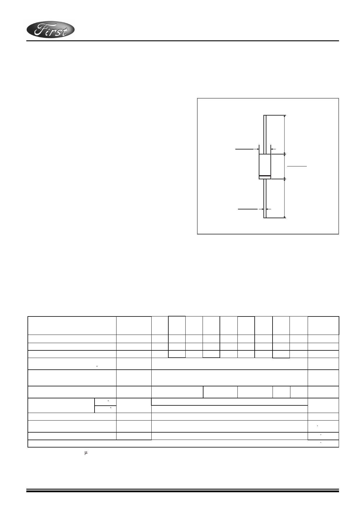
Package outline
Features
• Plastic package has Underwriters Laboratory Flammability
Classification 94V-0
• Guard ring for overvoltage protection
• Low power loss, high efficiency
• High current capability, Low forward voltage drop
• High surge capability
• For use in low voltage, high frequency inverters,
free wheeling, and polarity protection applications
• High temperature soldering guaranteed:
260 C/10 seconds at terminals
• Component in accordance to RoHS 2002/95/EC and
WEEE 2002/96/EC
Mechanical data
• Case: JEDEC DO-41 molded plastic body
• Terminals: Plated axial leads, solderable per MIL-STD-750,
Method 2026
• Polarity: Color band denotes cathode end
• Mounting Position: Any
• Weight: 0.012 ounce, 0.33 gram
DO-41
0.107(2.7)
0.080(2.0)
DIA.
1.0(25.4)
MIN
0.205(5.20)
0.161(4.10)
0.034(0.85)
0.028(0.65)
DIA.
1.0(25.4)
MIN
Dimensions in inches and (millimeters)
Maximum Ratings And Electrical Characteristics
• Ratings at 25 C ambient temperature unless otherwise specified.
• Single phase, half wave, resistive or inductive load.
• For capacitive load, derate by 20%.
Type Number
Symbols
MBR
220
TG
MBR
230
TG
MBR
240
TG
MBR
250
TG
MBR
260
TG
MBR
280
TG
MBR
2100
TG
MBR
2150
TG
MBR
2200
TG
Maximum repetitive peak reverse voltage
Maximum RMS voltage
Maximum DC blocking voltage
Maximum average forward rectified current
0.375"(9.5mm) lead length at TL=75 C
Peak forward surge current 8.3ms single half
sine-wave superimposed on rated load
(JEDEC method)
Maximum instantaneous forward voltage
at 2.0 A(Note 1 )
Maximum instantaneous reverse
current at rated DC blocking
voltage(Note 1)
TA =25 C
TA =100 C
Typical junction capacitance(Note 3)
VRRM
VRMS
VDC
I(AV)
IFSM
VF
IR
CJ
20 30 40 50 60 80 100 150 200
14 21 28 35 42 57 71 105 140
20 30 40 50 60 80 100 150 200
2.0
50.0
0.55
0.70
0.85
0.90 0.95
0.2
10
170
Typical thermal resistance(Note 2)
R JA
50
Operating junction temperature range
Storage temperature range
TJ
TSTG
-65 to+150
-65 to+150
Notes: 1.Pulse test: 300 s pulse width,1% duty cycle
2.Thermal resistance from junction to lead, and/or to ambient P.C.B. mounted with 0.375"(9.5mm) lead length
with 1.5 X1.5"(38X38mm)copper pads
3.Measured at 1.0MHz and reverse voltage of 4.0 volts
Units
Volts
Volts
Volts
Amps
Amps
Volts
mA
PF
C/W
C
C
@ 2010 Copyright By American First Semiconductor
Page 1/2
1 page | ||
| Páginas | Total 2 Páginas | |
| PDF Descargar | [ Datasheet MBR2100TG.PDF ] | |
Hoja de datos destacado
| Número de pieza | Descripción | Fabricantes |
| MBR2100TG | (MBR220TG - MBR2200TG) Schottky Barrier Rectifier | American First Semiconductor |
| Número de pieza | Descripción | Fabricantes |
| SLA6805M | High Voltage 3 phase Motor Driver IC. |
Sanken |
| SDC1742 | 12- and 14-Bit Hybrid Synchro / Resolver-to-Digital Converters. |
Analog Devices |
|
DataSheet.es es una pagina web que funciona como un repositorio de manuales o hoja de datos de muchos de los productos más populares, |
| DataSheet.es | 2020 | Privacy Policy | Contacto | Buscar |