|
|
|
PDF SHT71 Data sheet ( Hoja de datos )
| Número de pieza | SHT71 | |
| Descripción | Humidity and Temperature Sensor IC | |
| Fabricantes | Sensirion | |
| Logotipo | ||
Hay una vista previa y un enlace de descarga de SHT71 (archivo pdf) en la parte inferior de esta página. Total 12 Páginas | ||
|
No Preview Available !
Datasheet SHT7x (SHT71, SHT75)
Humidity and Temperature Sensor IC
Fully calibrated
Digital output
Low power consumption
Excellent long term stability
Pin type package – easy integration
Product Summary
SHT7x (including SHT71 and SHT75) is Sensirion’s family
of relative humidity and temperature sensors with pins.
The sensors integrate sensor elements plus signal
processing in compact format and provide a fully
calibrated digital output. A unique capacitive sensor
element is used for measuring relative humidity while
temperature is measured by a band-gap sensor. The
applied CMOSens® technology guarantees excellent
reliability and long term stability. Both sensors are
seamlessly coupled to a 14bit analog to digital converter
and a serial interface circuit. This results in superior signal
quality, a fast response time and insensitivity to external
disturbances (EMC).
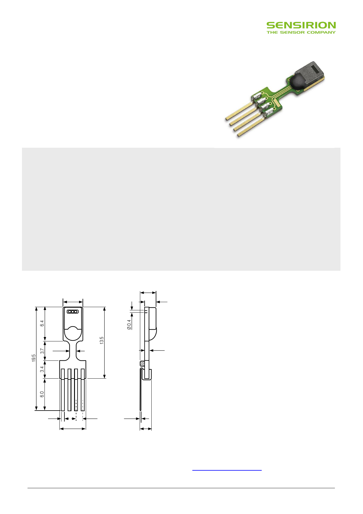
Dimensions
3.7
3.1
2.2
B2G
71
1.2
1234
0.6
0.46 1.27
5.08
0.2
2.0
Figure 1: Drawing of SHT7x (applies to SHT71 and SHT75)
sensor packaging, dimensions in mm (1mm = 0.039inch).
Contact assignment: 1: SCK, 2: VDD, 3: GND, 4: DATA.
Hatched item on backside of PCB is a 100nF capacitor – see
Section 2.1 for more information.
Each SHT7x is individually calibrated in a precision
humidity chamber. The calibration coefficients are
programmed into an OTP memory on the chip. These
coefficients are used to internally calibrate the signals
from the sensors. The 2-wire serial interface and internal
voltage regulation allows for easy and fast system
integration. The small size and low power consumption
makes SHT7x the ultimate choice for even the most
demanding applications.
SHT7x is supplied on FR4 with pins which allows for easy
integration or replacement. The same sensor is also
available as surface mountable packaging (SHT1x) or on
flex print (SHTA1).
Sensor Chip
SHT7x V4 – for which this datasheet applies – features a
version 4 Silicon sensor chip. Besides a humidity and a
temperature sensor the chip contains an amplifier, A/D
converter, OTP memory and a digital interface. V4 sensors
can be identified by the alpha-numeric traceability code on
the sensor cap – see example “B2G” code on Figure 1.
Material Contents
While the sensor is made of a CMOS chip the sensor
housing consists of an LCP cap with epoxy glob top on an
FR4 substrate. Pins are made of a Cu/Be alloy coated with
Ni and Au. The device is fully RoHS and WEEE compliant,
thus it is free of Pb, Cd, Hg, Cr(6+), PBB and PBDE.
Evaluation Kits
For sensor trial measurements, for qualification of the
sensor or even experimental application (data logging) of
the sensor there is an evaluation kit EK-H4 available
including SHT71 (same sensor chip as SHT1x) and 4
sensor channels, hard and software to interface with a
computer. For other evaluation kits please check
www.sensirion.com/humidity.
www.sensirion.com
Version 5 – December 2011
1/12
1 page 
Datasheet SHT7x
microcontrollers. See Table 2 for detailed I/O characteristic
of the sensor.
2.4 Electrical Characteristics
The electrical characteristics such as power consumption,
low and high level, input and output voltages depend on
the supply voltage. Table 2 gives electrical characteristics
of SHT7x with the assumption of 5V supply voltage if not
stated otherwise. For proper communication with the
sensor it is essential to make sure that signal design is
strictly within the limits given in Table 3 and Figure 6.
Absolute maximum ratings for VDD versus GND are +7V
and -0.3V. Exposure to absolute maximum rating
conditions for extended periods may affect the sensor
reliability (e.g. hot carrier degradation, oxide breakdown).
Parameter
Conditions
min typ max Units
Power supply DC10
2.4 3.3 5.5 V
measuring
0.55 1 mA
Supply current average11
2 28
µA
sleep 0.3 1.5 µA
Low level output
voltage
IOL < 4 mA
0
250 mV
High level output
voltage
RP < 25 kΩ
90%
100% VDD
Low level input
voltage
Negative going 0%
20% VDD
High level input
voltage
Positive going 80%
100% VDD
Input current on
pads
1 µA
Output current
on
Tri-stated (off)
4 mA
10 20 µA
Table 2: SHT7x DC characteristics. RP stands for pull up
resistor, while IOL is low level output current.
TSCK
SCK
TSU
TSCKH
TSCKL TR
TF
DATA valid write
THO
DATA valid read
TV
DATA
80%
20%
TRO
TFO
80%
20%
Figure 6: Timing Diagram, abbreviations are explained in
Table 3. Bold DATA line is controlled by the sensor, plain DATA
line is controlled by the micro-controller. Note that DATA valid
read time is triggered by falling edge of anterior toggle.
10 Recommended voltage supply for highest accuracy is 3.3V, due to sensor
calibration.
11 Minimum value with one measurement of 8 bit resolution without OTP reload
per second, typical value with one measurement of 12bit resolution per
second.
Parameter
FSCK SCK Frequency
Conditions min
VDD > 4.5V 0
VDD < 4.5V 0
typ max Units
0.1 5 MHz
0.1 1 MHz
TSCKx SCK hi/low time
100
TR/TF SCK rise/fall time
1 200 *
TFO DATA fall time
OL = 5pF 3.5 10 20
OL = 100pF 30 40 200
ns
ns
ns
ns
TRO DATA rise time
TV DATA valid time
TSU DATA setup time
THO DATA hold time
** ** **
200 250 ***
100 150 ***
10 15 ****
ns
ns
ns
ns
* TR_max + TF_max = (FSCK)-1 – TSCKH – TSCKL
** TR0 is determined by the RP*Cbus time-constant at DATA line
*** TV_max and TSU_max depend on external pull-up resistor (RP) and total bus
line capacitance (Cbus) at DATA line
**** TH0_max < TV – max (TR0, TF0)
Table 3: SHT7x I/O signal characteristics, OL stands for Output
Load, entities are displayed in Figure 6.
3 Communication with Sensor
3.1 Start up Sensor
As a first step the sensor is powered up to chosen supply
voltage VDD. The slew rate during power up shall not fall
below 1V/ms. After power-up the sensor needs 11ms to
get to Sleep State. No commands must be sent before
that time.
3.2 Sending a Command
To initiate a transmission, a Transmission Start sequence
has to be issued. It consists of a lowering of the DATA line
while SCK is high, followed by a low pulse on SCK and
raising DATA again while SCK is still high – see Figure 7.
SCK
80%
20%
DATA
80%
20%
Figure 7: "Transmission Start" sequence
The subsequent command consists of three address bits
(only ‘000’ is supported) and five command bits. The
SHT7x indicates the proper reception of a command by
pulling the DATA pin low (ACK bit) after the falling edge of
the 8th SCK clock. The DATA line is released (and goes
high) after the falling edge of the 9th SCK clock.
www.sensirion.com
Version 5 – December 2011
5/12
5 Page 
Datasheet SHT7x
Revision History
Date
March 2007
July 2008
April 2009
May 2010
December 2011
Version
3.0
4.0
4.2
4.3
5
Page(s)
1 – 10
1 – 10
2, 7
1 – 11
1, 7-9
Changes
Data sheet valid for SHTxx-V4 and SHTxx-V3
New release, rework of datasheet
Amended foot note 2, communication diagram changed (Figure 12)
Errors eliminated, information added – for details please ask for change protocol.
References to V3 sensors eliminated.
www.sensirion.com
Version 5 – December 2011
11/12
11 Page | ||
| Páginas | Total 12 Páginas | |
| PDF Descargar | [ Datasheet SHT71.PDF ] | |
Hoja de datos destacado
| Número de pieza | Descripción | Fabricantes |
| SHT71 | Humidity & Temperature Sensor | ETC |
| SHT71 | Humidity and Temperature Sensor IC | Sensirion |
| SHT75 | Humidity & Temperature Sensor | ETC |
| SHT75 | Humidity and Temperature Sensor IC | Sensirion |
| Número de pieza | Descripción | Fabricantes |
| SLA6805M | High Voltage 3 phase Motor Driver IC. |
Sanken |
| SDC1742 | 12- and 14-Bit Hybrid Synchro / Resolver-to-Digital Converters. |
Analog Devices |
|
DataSheet.es es una pagina web que funciona como un repositorio de manuales o hoja de datos de muchos de los productos más populares, |
| DataSheet.es | 2020 | Privacy Policy | Contacto | Buscar |