|
|
|
PDF HC5549 Data sheet ( Hoja de datos )
| Número de pieza | HC5549 | |
| Descripción | Low Power SLIC with Battery Switch | |
| Fabricantes | Intersil Corporation | |
| Logotipo | ||
Hay una vista previa y un enlace de descarga de HC5549 (archivo pdf) en la parte inferior de esta página. Total 13 Páginas | ||
|
No Preview Available !
Semiconductor
Data Sheet
HC5549
January 1999 File Number 4539.1
Low Power SLIC with Battery Switch
The HC5549 Subscriber line
interface circuit is a 100V
diellectrically isolated bipolar
integrated circuit for use in
short loop ISDN, PABX and
Pairgain applications. The HC5549 has been optimized for low
power as required for battery backed remote terminals or for
applications requiring emergency powering from the line such
as European ISDN NT1+ designs.
A high and low voltage battery supply may be connected to
the HC5549 so that power dissipation can be lowered in the
off hook condition in these short loop applications. The high
battery supply can be used in the on-hook condition to allow
interfacing to fax and answering machines that require 48V
to detect end of call status. The HC5549 also has a low
power standby state with very low power consumption
(35mW) resulting in exceptionally low battery drain while
providing continued loop supervision.
The HC5549 provides loop current, ground key and ring trip
detect functions as well as an alarm output to indicate
thermal overload.
2-wire to 4-wire and 4-wire to 2-wire conversion is provided
and impedance matching is achieved using a single external
network. The HC5549 is compatible with dual and single
supply switched capacitor or DSP codec/filters
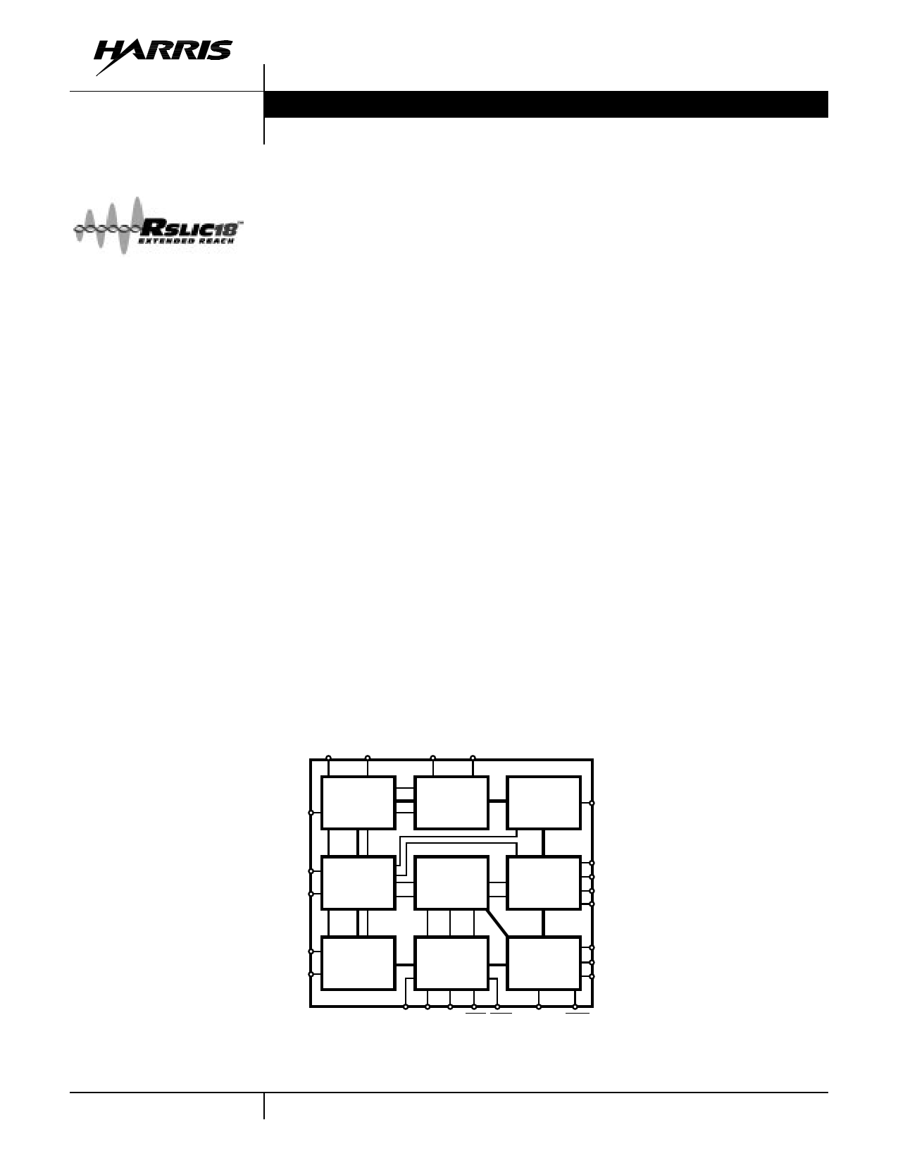
Block Diagram
Features
• Dual Battery Operation
• Single Additional +5V Supply
• Low Standby Power Consumption (48V, 35mW)
• On Hook Transmission
• Tip and Ring Disconnect
• Soft or Hard Polarity Reversal
• Supports 12 kHz or 16 kHz Pulse Metering
• Ring Relay Driver
• On Chip 2-wire AC/DC Loopback
• No Latch-Up or Power Supply Sequencing
• 0o to 70o or -40o to 85o Ambient Temp Range
• Low External Component Count
Applications
• ISDN NT1+ Terminals
• Pairgain Remote Termination
• PABX and Key Systems
Related Literature
• AC SPICE Macromodel
POL CDC
VBL VBH
ILIM
DC
CONTROL
BATTERY
SWITCH
RINGING
PORT
VRS
TIP
RING
2-WIRE
PORT
TRANSMIT
SENSING
4-WIRE
PORT
VRX
VTX
-IN
VFB
SW+
SW-
TEST
ACCESS
DETECTOR
LOGIC
CONTROL
LOGIC
F2
F1
F0
RTD RD E0 DET ALM BSEL SWC
4-80
CAUTION: These devices are sensitive to electrostatic discharge; follow proper IC Handling Procedures.
1-800-4-HARRIS or 407-727-9207 | Copyright © Harris Corporation 1999
RSLIC18™ is a trademark of Harris Corporation.
1 page 
HC5549
Design Equations
Loop Supervision Thresholds
SWITCH HOOK DETECT
The switch hook detect threshold is set by a single external
resistor, RSH. Equation 1 is used to calculate the value of RSH.
RSH = 600 ⁄ ISH
(EQ. 1)
The term ISH is the desired DC loop current threshold. The
loop current threshold programming range is from 5mA to
15mA.
GROUND KEY DETECT
The ground key detector senses a DC current imbalance
between the Tip and Ring terminals when the ring terminal is
connected to ground. The ground key detect threshold is not
externally programmable and is internally fixed to 12mA
regardless of the switch hook threshold.
RING TRIP DETECT
The ring trip detect threshold is set by a single external
resistor, RRT. IRT should be set between the peak ringing
current and the peak off hook current while still ringing.
RRT = 1800 ⁄ IRT
(EQ. 2)
The capacitor CRT, in parallel with RRT, will set the ring trip
response time.
Loop Current Limit
The loop current limit of the device is programmed by the
external resistor RIL. The value of RIL can be calculated
using Equation 3.
RIL = 1-I--L-7---I6--M-0--
(EQ. 3)
The term ILIM is the desired loop current limit. The loop
current limit programming range is from 15mA to 45mA.
Impedance Matching
The impedance of the device is programmed with the
external component RS. RS is the gain setting resistor for
the feedback amplifier that provides impedance matching. If
complex impedance matching is required, then a complex
network can be substituted for RS.
RESISTIVE IMPEDANCE SYNTHESIS
The source impedance of the device, ZO , can be calculated
in Equation 4.
RS = 400(ZO)
(EQ. 4)
The required impedance is defined by the terminating
impedance and protection resistors as shown in Equation 5.
ZO = ZL – 2RP
(EQ. 5)
4-WIRE TO 2-WIRE GAIN
The 4-wire to 2-wire gain is defined as the receive gain. It is
a function of the terminating impedance, synthesized
impedance and protection resistors. Equation 6 calculates
the receive gain, G42.
G42
=
–2
Z----O-------+-----2--Z--R--L---P-----+------Z----L-
(EQ. 6)
When the device source impedance and protection resistors
equals the terminating impedance, the receive gain equals
unity.
2-WIRE TO 4-WIRE GAIN
The 2-wire to 4-wire gain (G24) is the gain from tip and ring to
the VTX output. The transmit gain is calculated in Equation 7.
G24
=
–
Z----O-------+-----2--Z--R--O---P-----+------Z----L-
(EQ. 7)
When the protection resistors are set to zero, the transmit
gain is -6dB.
TRANSHYBRID GAIN
The transhybrid gain is defined as the 4-wire to 4-wire gain
(G44).
G44
=
–
-Z---O------+-----2-Z---R-O---P-----+-----Z----L-
(EQ. 8)
When the protection resistors are set to zero, the transhybrid
gain is -6dB.
COMPLEX IMPEDANCE SYNTHESIS
Substituting the impedance programming resistor, RS, with a
complex programming network provides complex
impedance synthesis.
2-WIRE
NETWORK
C2
R1
R2
PROGRAMMING
NETWORK
CP
RS
RP
FIGURE 1. COMPLEX PROGRAMMING NETWORK
The reference designators in the programming network
match the evaluation board. The component RS has a
different design equation than the RS used for resistive
impedance synthesis. The design equations for each
component are provided below.
RS = 400 × (R1 – 2(RP))
(EQ. 9)
RP = 400 × R2
CP = C2 ⁄ 400
(EQ. 10)
(EQ. 11)
4-84
5 Page 
HC5549
Uncommitted Switch
Overview
The uncommitted switch is a three terminal device designed
for flexibility. The independent logic control input, SWC,
allows switch operation regardless of device operating
mode. The switch is activated by a logic low. The positive
and negative terminals of the device are labeled SW+ and
SW- respectively.
Relay Driver
The uncommitted switch may be used as a relay driver by
connecting SW+ to the relay coil and SW- to ground. The
switch is designed to have a maximum on voltage of 0.6V
with a load current of 45mA.
+5V
RELAY
SW+
SW-
SWC
FIGURE 9. EXTERNAL RELAY SWITCHING
Since the device provides the ringing waveform, the relay
functions which may be supported include subscriber
disconnect, test access or line interface bypass. An external
snubber diode is not required when using the uncommitted
switch as a relay driver.
Test Load
The switch may be used to connect test loads across Tip
and Ring. The test loads can provide external test
termination for the device. Proper connection of the
uncommitted switch to Tip and Ring is shown below.
TIP
RING
TEST
LOAD
SW+
SW-
SWC
FIGURE 10. TEST LOAD SWITCHING
The diode in series with the test load blocks current from
flowing through the uncommitted switch when the polarity of
the Tip and Ring terminals are reversed. In addition to the
reverse active state, the polarity of Tip and Ring are reversed
for half of the ringing cycle. With independent logic control
and the blocking diode, the uncommitted switch may be
continuously connected to the Tip and Ring terminals.
4-90
11 Page | ||
| Páginas | Total 13 Páginas | |
| PDF Descargar | [ Datasheet HC5549.PDF ] | |
Hoja de datos destacado
| Número de pieza | Descripción | Fabricantes |
| HC5549 | Low Power SLIC with Battery Switch | Intersil Corporation |
| Número de pieza | Descripción | Fabricantes |
| SLA6805M | High Voltage 3 phase Motor Driver IC. |
Sanken |
| SDC1742 | 12- and 14-Bit Hybrid Synchro / Resolver-to-Digital Converters. |
Analog Devices |
|
DataSheet.es es una pagina web que funciona como un repositorio de manuales o hoja de datos de muchos de los productos más populares, |
| DataSheet.es | 2020 | Privacy Policy | Contacto | Buscar |