|
|
|
PDF IRFH5220TRPBF Data sheet ( Hoja de datos )
| Número de pieza | IRFH5220TRPBF | |
| Descripción | HEXFET Power MOSFET | |
| Fabricantes | International Rectifier | |
| Logotipo | ||
Hay una vista previa y un enlace de descarga de IRFH5220TRPBF (archivo pdf) en la parte inferior de esta página. Total 8 Páginas | ||
|
No Preview Available !
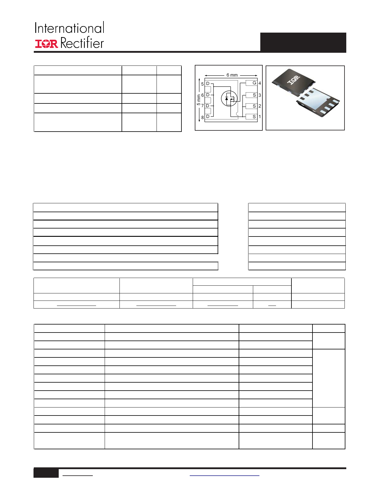
VDS
RDS(on) max
(@VGS = 10V)
Qg (typical)
RG (typical)
ID
(@Tc(Bottom) = 25°C)
200 V
99.9 mΩ
20 nC
2.3 Ω
20 A
IRFH5220PbF
HEXFET® Power MOSFET
PQFN 5X6 mm
Applications
• Secondary Side Synchronous Rectification
• Inverters for DC Motors
• DC-DC Brick Applications
• Boost Converters
Features and Benefits
Features
Benefits
Low RDSon
Low Thermal Resistance to PCB (≤ 1.2°C/W)
100% Rg tested
Low Profile (≤ 0.9 mm)
Lower Conduction Losses
Enable better thermal dissipation
Increased Reliability
results in Increased Power Density
Industry-Standard Pinout
⇒ Multi-Vendor Compatibility
Compatible with Existing Surface Mount Techniques
Easier Manufacturing
RoHS Compliant Containing no Lead, no Bromide and no Halogen
Environmentally Friendlier
MSL1, Industrial Qualification
Increased Reliability
Orderable part number
IRFH5220TRPBF
IRFH5220TR2PBF
Package Type
PQFN 5mm x 6mm
PQFN 5mm x 6mm
Standard Pack
Form
Quantity
Tape and Reel
4000
Tape and Reel
400
Note
EOL notice # 259
Absolute Maximum Ratings
Parameter
VDS
VGS
ID @ TA = 25°C
ID @ TA = 70°C
ID @ TC(Bottom) = 25°C
ID @ TC(Bottom) = 100°C
ID @ TC(Top) = 25°C
ID @ TC(Top) = 100°C
IDM
PD @TA = 25°C
PD @ TC(Top) = 25°C
Drain-to-Source Voltage
Gate-to-Source Voltage
Continuous Drain Current, VGS @ 10V
Continuous Drain Current, VGS @ 10V
Continuous Drain Current, VGS @ 10V
Continuous Drain Current, VGS @ 10V
Continuous Drain Current, VGS @ 10V
cContinuous Drain Current, VGS @ 10V
Pulsed Drain Current
gPower Dissipation
fPower Dissipation
fLinear Derating Factor
TJ
TSTG
Operating Junction and
Storage Temperature Range
Notes through
are on page 8
Max.
200
± 20
3.8
3.0
20
13
5.8
3.7
47
3.6
8.3
0.07
-55 to + 150
Units
V
A
W
W/°C
°C
1 www.irf.com © 2014 International Rectifier
Submit Datasheet Feedback
May 13, 2014
1 page 
200
ID = 5.8A
160
TJ = 125°C
120
80
40
4
TJ = 25°C
8 12 16
VGS, Gate-to-Source Voltage (V)
20
Fig 12. On-Resistance vs. Gate Voltage
IRFH5220PbF
1200
1000
800
ID
TOP 0.98A
1.4A
BOTTOM 5.8A
600
400
200
0
25
50 75 100 125 150
Starting TJ, Junction Temperature (°C)
Fig 13. Maximum Avalanche Energy vs. Drain Current
15V
VDS
L
RG
20V
tp
D.U.T
IAS
0.01Ω
DRIVER
+
-
VDD
A
Fig 14a. Unclamped Inductive Test Circuit
V(BR)DSS
tp
IAS
Fig 14b. Unclamped Inductive Waveforms
VDS
VGS
RG
RD
D.U.T.
V1G0SV
Pulse Width ≤ 1 µs
Duty Factor ≤ 0.1
+-VDD
Fig 15a. Switching Time Test Circuit
VDS
90%
10%
VGS
td(on) tr
td(off) tf
Fig 15b. Switching Time Waveforms
5 www.irf.com © 2014 International Rectifier
Submit Datasheet Feedback
May 13, 2014
5 Page | ||
| Páginas | Total 8 Páginas | |
| PDF Descargar | [ Datasheet IRFH5220TRPBF.PDF ] | |
Hoja de datos destacado
| Número de pieza | Descripción | Fabricantes |
| IRFH5220TRPBF | HEXFET Power MOSFET | International Rectifier |
| Número de pieza | Descripción | Fabricantes |
| SLA6805M | High Voltage 3 phase Motor Driver IC. |
Sanken |
| SDC1742 | 12- and 14-Bit Hybrid Synchro / Resolver-to-Digital Converters. |
Analog Devices |
|
DataSheet.es es una pagina web que funciona como un repositorio de manuales o hoja de datos de muchos de los productos más populares, |
| DataSheet.es | 2020 | Privacy Policy | Contacto | Buscar |