|
|
|
PDF HCS245MS Data sheet ( Hoja de datos )
| Número de pieza | HCS245MS | |
| Descripción | Radiation Hardened Octal Bus Transceiver/ Three-State/ Non-Inverting | |
| Fabricantes | Intersil Corporation | |
| Logotipo | ||
Hay una vista previa y un enlace de descarga de HCS245MS (archivo pdf) en la parte inferior de esta página. Total 7 Páginas | ||
|
No Preview Available !
HCS245MS
December 1992
Radiation Hardened
Octal Bus Transceiver, Three-State, Non-Inverting
Features
• 3 Micron Radiation Hardened CMOS SOS
• Total Dose 200K or 1 Mega-RAD(Si)
• Latch-Up Free Under Any Conditions
• Fanout (Over Temperature Range)
- Bus Driver Outputs - 15 LSTTL Loads
• Military Temperature Range: -55oC to +125oC
• Significant Power Reduction Compared to LSTTL ICs
• DC Operating Voltage Range: 4.5V to 5.5V
• LSTTL Input Compatibility
- VIL = 0.8V Max
- VIH = VCC/2 Min
• Input Current Levels Ii ≤ 5µA at VOL, VOH
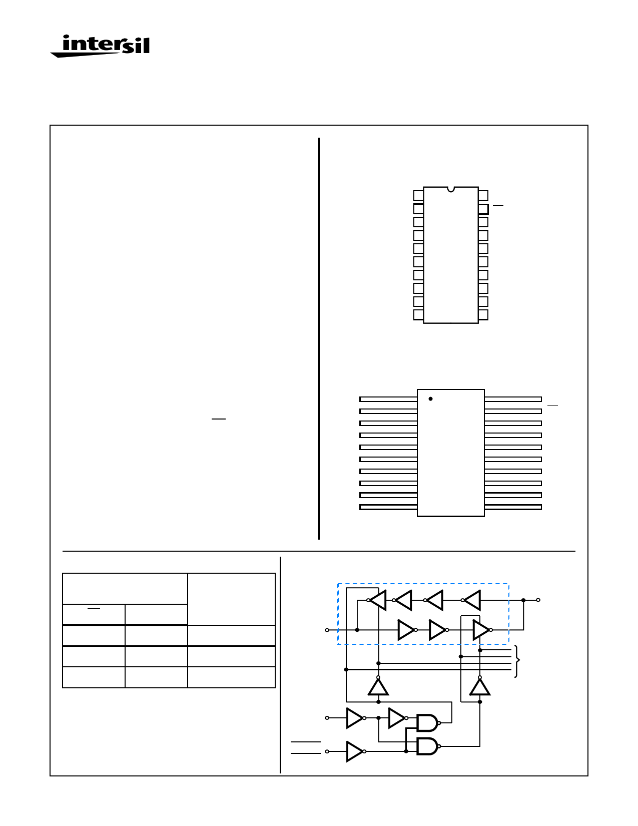
Pinouts
20 PIN CERAMIC DUAL-IN-LINE
MIL-STD-1835 DESIGNATOR CDIP2-T20, LEAD FINISH C
TOP VIEW
DIR 1
A0 2
A1 3
A2 4
A3 5
A4 6
A5 7
A6 8
A7 9
GND 10
20 VCC
19 OE
18 B0
17 B1
16 B2
15 B3
14 B4
13 B5
12 B6
11 B7
Description
The Intersil HCS245MS is a Radiation Hardened Non-Invert-
ing Octal Bidirectional Bus Transceiver, Three-State,
intended for two-way asynchronous communication between
data busses. The HCS245MS allows data transmission from
the A bus to the B bus or from the B bus to the A bus. The
logic level at the direction input (DIR) determines the data
direction. The output enable input (OE) puts the I/O port in
the high-impedance state when high.
The HCS245MS utilizes advanced CMOS/SOS technology
to achieve high-speed operation. This device is a member of
radiation hardened, high-speed, CMOS/SOS Logic Family.
The HCS245MS is supplied in a 20 lead Weld Seal Ceramic
flatpack (K suffix) or a Weld Seal Ceramic Dual-In-Line
Package (D suffix).
20 PIN CERAMIC FLAT PACK
MIL-STD-1835 DESIGNATOR CDFP4-F20, LEAD FINISH C
TOP VIEW
DIR
A0
A1
A2
A3
A4
A5
A6
A7
GND
1 20
2 19
3 18
4 17
5 16
6 15
7 14
8 13
9 12
10 11
VCC
OE
B0
B1
B2
B3
B4
B5
B6
B7
Truth Table
CONTROL
INPUTS
OE DIR OPERATION
L L B Data to A Bus
L H A Data to B Bus
H X Isolation
H = High Voltage Level, L = Low Voltage Level,
X = Immaterial
To prevent excess currents in the High-Z (Isolation)
modes, all I/O terminals should be terminated with 10kΩ
to 1MΩ resistors.
Functional Diagram
ONE OF 8 TRANSCEIVERS
B DATA
11
(18, 17, 16, 15,
14, 13, 12)
DIR
1
OUTPUT
ENABLE 19
A DATA
9
(2, 3, 4, 5,
6, 7, 8)
TO OTHER
7 BUFFERS
CAUTION: These devices are sensitive to electrostatic discharge; follow proper IC Handling Procedures.
1-888-INTERSIL or 321-724-7143 | Copyright © Intersil Corporation 1999
7-475
File Number 2468.1
1 page 
Specifications HCS245MS
TABLE 8. STATIC BURN-IN AND DYNAMIC BURN-IN TEST CONNECTIONS
OPEN
GROUND
1/2 VCC = 3V ± 0.5V
VCC = 6V ± 0.5V
STATIC BURN-IN I TEST CONNECTIONS (Note 1)
2-9
1, 10 - 19
-
20
STATIC BURN-IN II TEST CONNECTIONS (Note 1)
- 10
- 1 - 9, 11 - 20
DYNAMIC BURN-IN TEST CONNECTIONS (Note 2)
- 10
11 - 18
1, 20
NOTES:
1. Each pin except VCC and GND will have a resistor of 10KΩ ± 5% for static burn-in.
2. Each pin except VCC and GND will have a resistor of 680Ω ± 5% for dynamic burn-in.
OSCILLATOR
50kHz
25kHz
--
--
2-9
19
TABLE 9. IRRADIATION TEST CONNECTIONS
OPEN
GROUND
VCC = 5V ± 0.5V
- 10 1 - 9, 11 - 20
NOTE: Each pin except VCC and GND will have a resistor of 47KΩ ± 5% for irradiation testing. Group E, Sub-
group 2, sample size is 4 dice/wafer 0 failures.
AC Timing Diagrams
VIH
VIL
VOH
VOL
VS INPUT
TPLH
VS
TPHL
OUTPUT
VOH
VOL
TTLH
20%
80% 80%
OUTPUT
AC VOLTAGE LEVELS
TTHL
20%
PARAMETER
VCC
VIH
VS
VIL
GND
HCS
4.50
4.50
2.25
0
0
UNITS
V
V
V
V
V
AC Load Circuit
DUT
CL
CL = 50pF
RL = 500Ω
7-479
TEST
POINT
RL
5 Page | ||
| Páginas | Total 7 Páginas | |
| PDF Descargar | [ Datasheet HCS245MS.PDF ] | |
Hoja de datos destacado
| Número de pieza | Descripción | Fabricantes |
| HCS245MS | Radiation Hardened Octal Bus Transceiver/ Three-State/ Non-Inverting | Intersil Corporation |
| Número de pieza | Descripción | Fabricantes |
| SLA6805M | High Voltage 3 phase Motor Driver IC. |
Sanken |
| SDC1742 | 12- and 14-Bit Hybrid Synchro / Resolver-to-Digital Converters. |
Analog Devices |
|
DataSheet.es es una pagina web que funciona como un repositorio de manuales o hoja de datos de muchos de los productos más populares, |
| DataSheet.es | 2020 | Privacy Policy | Contacto | Buscar |