|
|
|
PDF IRLTS2242PbF Data sheet ( Hoja de datos )
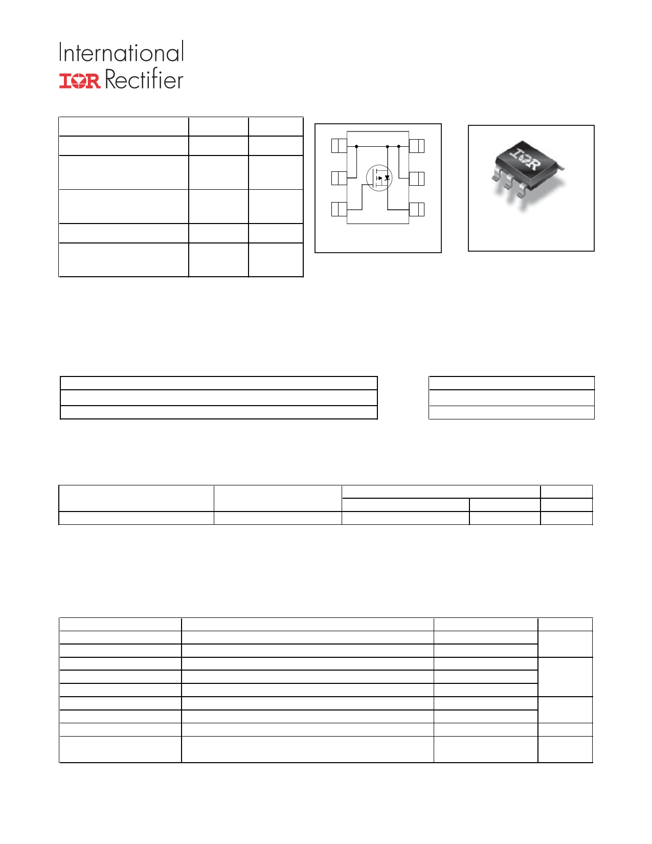
| Número de pieza | IRLTS2242PbF | |
| Descripción | HEXFET Power MOSFET | |
| Fabricantes | International Rectifier | |
| Logotipo | ||
Hay una vista previa y un enlace de descarga de IRLTS2242PbF (archivo pdf) en la parte inferior de esta página. Total 8 Páginas | ||
|
No Preview Available !
VDS
VGS max
RDS(on) max
(@VGS = -4.5V)
RDS(on) max
(@VGS = -2.5V)
Qg typ
ID
(@TA= 25°C)
-20 V
±12 V
32 m
55 m
12 nC
-6.9 A
Applications
l Battery operated DC motor inverter MOSFET
l System/Load Switch
PD - 97729A
IRLTS2242PbF
HEXFET® Power MOSFET
D1
6
A
D
D2
5D
G3
4S
Top View
TSOP-6
Features and Benefits
Features
Benefits
Industry-Standard TSOP-6 Package
results in Multi-Vendor Compatibility
RoHS Compliant Containing no Lead, no Bromide and no Halogen Environmentally Friendlier
MSL1, Consumer Qualification
Increased Reliability
Orderable part number
IRLTS2242TRPbF
Package Type
TSOP-6
Standard Pack
Form
Quantity
Tape and Reel
3000
Note
Absolute Maximum Ratings
Parameter
VDS Drain-to-Source Voltage
VGS
ID @ TA = 25°C
ID @ TA = 70°C
IDM
PD @TA = 25°C
PD @TA = 70°C
Gate-to-Source Voltage
Continuous Drain Current, VGS @ 4.5V
cContinuous Drain Current, VGS @ 4.5V
Pulsed Drain Current
Power Dissipation
Power Dissipation
TJ
TSTG
Linear Derating Factor
Operating Junction and
Storage Temperature Range
Notes through are on page 2
www.irf.com
Max.
-20
±12
-6.9
-5.5
-55
2.0
1.3
0.02
-55 to + 150
Units
V
A
W
W/°C
°C
1
02/23/12
1 page 
70
ID = -6.9A
60
50
40
30 TJ = 125°C
20
TJ = 25°C
10
0
0 5 10 15 20
-VGS, Gate -to -Source Voltage (V)
Fig 12. On-Resistance vs. Gate Voltage
120
ID
100 TOP -1.3A
-2.0A
BOTTOM -5.5A
80
60
40
20
0
25 50 75 100 125 150
Starting TJ , Junction Temperature (°C)
Fig 14. Maximum Avalanche Energy vs. Drain Current
IRLTS2242PbF
450
400
350
Vgs = -2.5V
300
250
200
150
100 Vgs = -4.5V
50
0
0 10 20 30 40 50 60
-ID, Drain Current (A)
Fig 13. Typical On-Resistance vs. Drain Current
16000
14000
12000
10000
8000
6000
4000
2000
0
1E-8
1E-7
1E-6 1E-5
Time (sec)
1E-4
Fig 15. Typical Power vs. Time
1E-3
D.U.T *
+
-
RG
+
Circuit Layout Considerations
Low Stray Inductance
-
Ground Plane
Low Leakage Inductance
Current Transformer
- +
di/dt controlled by RG
Driver same type as D.U.T.
ISD controlled by Duty Factor "D"
D.U.T. - Device Under Test
VDD
+
-
* Reverse Polarity of D.U.T for P-Channel
Driver Gate Drive
P.W.
Period
D=
P.W.
Period
*VGS=10V
D.U.T. ISD Waveform
Reverse
Recovery
Current
Body Diode Forward
Current
di/dt
D.U.T. VDS Waveform
Diode Recovery
dv/dt
Re-Applied
Voltage
Body Diode
InIndduucctotor rCCuurrernetnt
Forward Drop
Ripple 5%
* VGS = 5V for Logic Level Devices
VDD
ISD
Fig 16. Diode Reverse Recovery Test Circuit for P-Channel HEXFET® Power MOSFETs
www.irf.com
5
5 Page | ||
| Páginas | Total 8 Páginas | |
| PDF Descargar | [ Datasheet IRLTS2242PbF.PDF ] | |
Hoja de datos destacado
| Número de pieza | Descripción | Fabricantes |
| IRLTS2242PbF | HEXFET Power MOSFET | International Rectifier |
| Número de pieza | Descripción | Fabricantes |
| SLA6805M | High Voltage 3 phase Motor Driver IC. |
Sanken |
| SDC1742 | 12- and 14-Bit Hybrid Synchro / Resolver-to-Digital Converters. |
Analog Devices |
|
DataSheet.es es una pagina web que funciona como un repositorio de manuales o hoja de datos de muchos de los productos más populares, |
| DataSheet.es | 2020 | Privacy Policy | Contacto | Buscar |