|
|
|
PDF MT9V032 Data sheet ( Hoja de datos )
| Número de pieza | MT9V032 | |
| Descripción | 1/3-Inch Wide-VGA CMOS Digital Image Sensor | |
| Fabricantes | Micron | |
| Logotipo | ||
Hay una vista previa y un enlace de descarga de MT9V032 (archivo pdf) en la parte inferior de esta página. Total 13 Páginas | ||
|
No Preview Available !
Preliminary‡
MT9V032: 1/3-Inch Wide-VGA Digital Image Sensor
Features
1/3-Inch Wide-VGA CMOS Digital Image
Sensor
MT9V032C12STM (Monochrome, Pb-Free)
MT9V032C12STC (Color, Pb-Free)
Features
• Micron® DigitalClarity® CMOS imaging technology
• Array format: Wide-VGA, active 752H x 480V
(360,960 pixels)
• Global shutter photodiode pixels; simultaneous
integration and readout
• Monochrome or color: Near_IR enhanced
performance for use with non-visible NIR
illumination
• Readout modes: Progressive or interlaced
• Shutter efficiency: >99%
• Simple two-wire serial interface
• Register lock capability
• Window size: User programmable to any smaller
format (QVGA, CIF, QCIF, and so on). Data rate can
be maintained independent of window size
• Binning: 2 x 2 and 4 x 4 of the full resolution
• ADC: On-chip, 10-bit column-parallel (option to
operate in 12-bit to 10-bit companding mode)
• Automatic controls: Auto exposure control (AEC)
and auto gain control (AGC); variable regional and
variable weight AEC/AGC
• Support for four unique serial control register IDs to
control multiple imagers on the same bus
• Data output formats:
• Single sensor mode:
10-bit parallel/stand-alone
8-bit or 10-bit serial LVDS
• Stereo sensor mode:
Interspersed 8-bit serial LVDS
Applications
• Security
• High dynamic range imaging
• Unattended surveillance
• Stereo vision
• Video as input
• Machine vision
• Automation
• Traffic camera
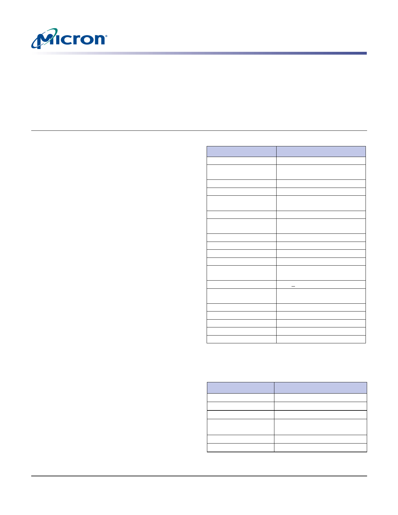
Table 1: Key Performance Parameters
Parameter
Value
Optical format
Active imager size
1/3-inch
4.51mm(H) x 2.88mm(V)
5.35mm diagonal
Active pixels
752H x 480V
Pixel size
Color filter array
6.0µm x 6.0µm
Monochrome or color RGB
Bayer pattern
Shutter type
Global shutter—TrueSNAP™
Maximum data rate/
master clock
Full resolution
Frame rate
26.6 MPS/26.6 MHz
752 x 480
60 fps (at full resolution)
ADC resolution
10-bit column-parallel
Responsivity
4.8 V/lux-sec (550nm)
Dynamic range
Supply voltage
Power consumption
>55dB linear;
>80−100dB in HiDy mode
3.3V +0.3V (all supplies)
<320mW at maximum data
rate; 100µW standby current
Operating temperature
Packaging
Output gain
Read noise
Dark current
–30°C to +70°C
48-pin CLCC
15.3 e-/LSB
25 e-PRMS at 1X
9,042 e-/pix/s at 55°C
Ordering Information
Table 2: Available Part Numbers
Part Number
MT9V032C12STM ES
MT9V032C12STC ES
MT9V032C12STMD ES
MT9V032C12STMH ES
MT9V032C12STCD ES
MT9V032C12STCH ES
Description
48-pin CLCC (mono)
48-pin CLCC (color)
Demo kit (mono)
Demo kit headboard only
(mono)
Demo kit (color)
Demo kit headboard only (color)
PDF: 09005aef824c9998/Source: 09005aef824c999c
MT9V032_LDS_1.fm - Rev. B 3/07 EN
1 Micron Technology, Inc., reserves the right to change products or specifications without notice.
©2006 Micron Technology, Inc. All rights reserved.
1 page 
Preliminary‡
MT9V032: 1/3-Inch Wide-VGA Digital Image Sensor
Pin Descriptions
Table 3:
Pin Descriptions
Only pins DOUT0 through DOUT9 may be tri-stated
Pin Number
29
10
Symbol
RSVD
SER_DATAIN_N
11 SER_DATAIN_P
8 BYPASS_CLKIN_N
9 BYPASS_CLKIN_P
23 EXPOSURE
25 SCLK
28 OE
30 S_CTRL_ADR0
31 S_CTRL_ADR1
32 RESET#
33 STANDBY
47 SYSCLK
24 SDATA
22 STLN_OUT
26 STFRM_OUT
20 LINE_VALID
21 FRAME_VALID
15 DOUT5
16 DOUT6
17 DOUT7
18 DOUT8
19 DOUT9
27 LED_OUT
41 DOUT4
42 DOUT3
43 DOUT2
44 DOUT1
45 DOUT0
46 PIXCLK
2 SHFT_CLKOUT_N
3 SHFT_CLKOUT_P
4 SER_DATAOUT_N
5 SER_DATAOUT_P
Type
Input
Input
Input
Input
Input
Input
Input
Input
Input
Input
Input
Input
Input
I/O
I/O
I/O
Output
Output
Output
Output
Output
Output
Output
Output
Output
Output
Output
Output
Output
Output
Output
Output
Output
Output
Description
Connect to DGND.
Serial data in for stereoscopy (differential negative). Tie to
1kΩ pull-up (to 3.3V) in non-stereoscopy mode.
Serial data in for stereoscopy (differential positive). Tie to
DGND in non-stereoscopy mode.
Input bypass shift-CLK (differential negative). Tie to 1KΩ
pull-up (to 3.3V) in non-stereoscopy mode.
Input bypass shift-CLK (differential positive). Tie to DGND
in non-stereoscopy mode.
Rising edge starts exposure in slave mode.
Two-wire serial interface clock. Connect to VDD with 1.5K
resistor even when no other two-wire serial interface
peripheral is attached.
DOUT enable pad, active HIGH.
Two-wire serial interface slave address bit 3.
Two-wire serial interface slave address bit 5.
Asynchronous reset. All registers assume defaults.
Shut down sensor operation for power saving.
Master clock (26.6 MHz).
Two-wire serial interface data. Connect to VDD with 1.5K
resistor even when no other two-wire serial interface
peripheral is attached.
Output in master mode—start line sync to drive slave chip
in-phase; input in slave mode.
Output in master mode—start frame sync to drive a slave
chip in-phase; input in slave mode.
Asserted when DOUT data is valid.
Asserted when DOUT data is valid.
Parallel pixel data output 5.
Parallel pixel data output 6.
Parallel pixel data output 7.
Parallel pixel data output 8
Parallel pixel data output 9.
LED strobe output.
Parallel pixel data output 4.
Parallel pixel data output 3.
Parallel pixel data output 2.
Parallel pixel data output 1.
Parallel pixel data output 0.
Pixel clock out. DOUT is valid on rising edge of this clock.
Output shift CLK (differential negative).
Output shift CLK (differential positive).
Serial data out (differential negative).
Serial data out (differential positive).
Notes
1
2
PDF: 09005aef824c9998/Source: 09005aef824c999c
MT9V032_LDS_2.fm - Rev. B 3/07 EN
5 Micron Technology, Inc., reserves the right to change products or specifications without notice.
©2006 Micron Technology, Inc. All rights reserved.
5 Page 
Preliminary‡
MT9V032: 1/3-Inch Wide-VGA Digital Image Sensor
Appendix A – Serial Configurations
Configuration of Sensor for Stereoscopic Serial Output with Internal PLL
In this configuration the internal PLL generates the shift-clk (x18) in phase with the
system-clock. The LVDS pins SER_DATAOUT_P and SER_DATAOUT_N must be
connected to a deserializer (clocked at approximately the same system clock frequency).
Figure 7 shows how a standard off-the-shelf deserializer can be used to retrieve back
DOUT(9:2) for both the master and slave sensors. Additional logic is required to extract
out LINE_VALID and FRAME_VALID embedded within the pixel data stream.
Figure 7: Stereoscopic Topology
SLAVE
MASTER
LVDS
SER_DATAIN
LVDS
BYPASS_CLKIN
SSEENNSSOORR
LVDS
SER_DATAIN
LVDS
BYPASS_CLKIN
X 1 8/X 1 2 PL L
LVDS
SER_DATAOUT
LVDS
SHIFT_CLKOUT
SENSOR
26.6 MHz
Osc.
LVDS
SER_DATAOUT
LVDS
SHIFT_CLKOUT
1. PLL in non-bypass mode
2. PLL in x 18 mode (stereoscopy)
1. PLL in bypass mode
DS92LV16
88
26.6 MHz
Osc.
PIXEL
FROM
SLAVE
PIXEL
FROM
MASTER
LV and FV are embedded in the data stream
5 meters (maximum)
Typical configuration of the master and slave sensors:
1. Power up the sensors.
2. Broadcast WRITE to de-assert LVDS power-down (set R0xB1[1] = 0).
3. Individual WRITE to master sensor putting its internal PLL into bypass mode (set
R0xB1[0] = 1).
4. Broadcast WRITE to both sensors to set the stereoscopy bit (set R0x07[5] = 1).
5. Make sure all resolution, vertical blanking, horizontal blanking, window size, and
AEC/AGC configurations are done through broadcast WRITE to maintain lockstep.
6. Broadcast WRITE to enable LVDS driver (set R0xB3[4] = 0).
7. Broadcast WRITE to enable LVDS receiver (set R0xB2[4] = 0).
8. Individual WRITE to master sensor, putting its internal PLL into bypass mode (set
R0xB1[0] = 1).
9. Individual WRITE to slave sensor, enabling its internal PLL (set R0xB1[0] = 0).
10. Individual WRITE to slave sensor, setting it as a stereo slave (set R0x07[6] = 1).
11. Individual WRITEs to master sensor to minimize the inter-sensor skew (set
R0xB2[2:0], R0xB3[2:0], and R0xB4[1:0] appropriately). Use R0xB7 and R0xB8 to get
lockstep feedback from stereo_error_flag.
12. Broadcast WRITE to issue a soft reset (set R0x0C[0] = 1 followed by R0x0C[0] = 0).
Note:
The stereo_error_flag is set if a mismatch has occurred at a reserved byte (slave and
master sensor’s codes at this reserved byte must match). If the flag is set, steps 11 and
12 are repeated until the stereo_error_flag remains cleared.
PDF: 09005aef824c9998/Source: 09005aef824c999c
MT9V032_LDS_2.fm - Rev. B 3/07 EN
11
Micron Technology, Inc., reserves the right to change products or specifications without notice.
©2006 Micron Technology, Inc. All rights reserved.
11 Page | ||
| Páginas | Total 13 Páginas | |
| PDF Descargar | [ Datasheet MT9V032.PDF ] | |
Hoja de datos destacado
| Número de pieza | Descripción | Fabricantes |
| MT9V032 | 1/3-Inch Wide-VGA CMOS Digital Image Sensor | Aptina Imaging Corporation |
| MT9V032 | 1/3-Inch Wide-VGA CMOS Digital Image Sensor | Micron |
| MT9V032 | 1/3-Inch Wide-VGA CMOS Digital Image Sensor | ON Semiconductor |
| MT9V032C12STC | 1/3-Inch Wide-VGA CMOS Digital Image Sensor | Aptina Imaging Corporation |
| Número de pieza | Descripción | Fabricantes |
| SLA6805M | High Voltage 3 phase Motor Driver IC. |
Sanken |
| SDC1742 | 12- and 14-Bit Hybrid Synchro / Resolver-to-Digital Converters. |
Analog Devices |
|
DataSheet.es es una pagina web que funciona como un repositorio de manuales o hoja de datos de muchos de los productos más populares, |
| DataSheet.es | 2020 | Privacy Policy | Contacto | Buscar |