|
|
|
PDF NE555 Data sheet ( Hoja de datos )
| Número de pieza | NE555 | |
| Descripción | PRECISION TIMERS | |
| Fabricantes | Diodes | |
| Logotipo | ||
 1. Bipolar Timer ( PDF ) Hay una vista previa y un enlace de descarga de NE555 (archivo pdf) en la parte inferior de esta página. Total 14 Páginas | ||
|
No Preview Available !
NE555/SA555/NA555
PRECISION TIMERS
Description
These devices are precision timing circuits capable of
producing accurate time delays or oscillation. In the time-
delay or monostable mode of operation, the timed interval is
controlled by a single external resistor and capacitor network.
In the astable mode of operation, the frequency and duty
cycle can be controlled independently with two external
resistors and a single external capacitor.
The threshold and trigger levels normally are two-thirds and
one-third, respectively, of VCC. These levels can be altered
by use of the control-voltage terminal. When the trigger input
falls below the trigger level, the flip-flop is set, and the output
goes high. If the trigger input is above the trigger level and
the threshold input is above the threshold level, the flip-flop is
reset and the output is low. The reset (RESET) input can
override all other inputs and can be used to initiate a new
timing cycle. When RESET goes low, the flip-flop is reset,
and the output goes low. When the output is low, a low-
impedance path is provided between discharge (DISCH) and
ground.
The output circuit is capable of sinking or sourcing current up
to 200mA. Operation is specified for supplies of 5V to 15V.
With a 5-V supply, output levels are compatible with TTL
inputs.
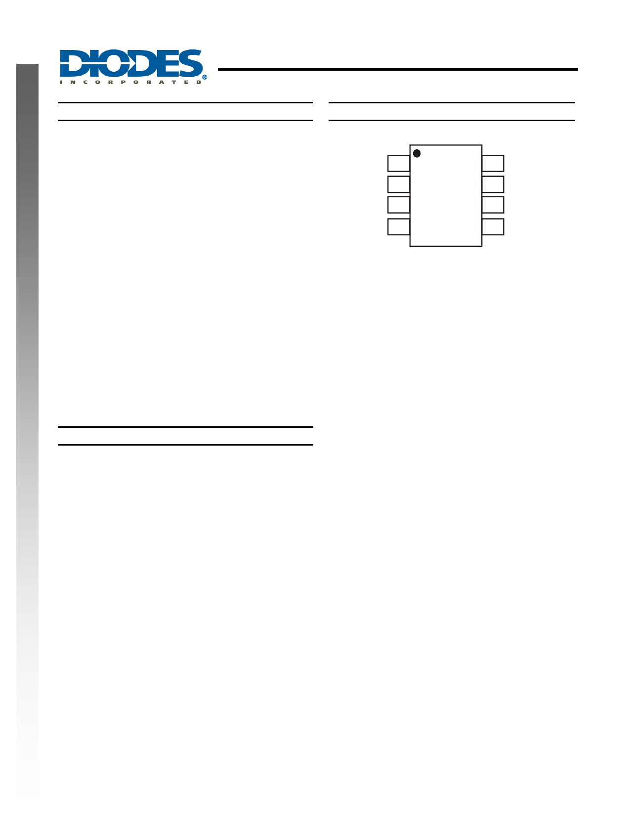
Pin Assignments
(Top View)
GND
TRIG
OUT
RESET
SO-8
Features
• Timing from microseconds to hours
• Astable or monostable operation
• Adjustable duty cycle
• TTL compatible output can source or sink up to 200mA
• “Green” Molding Compound (No Br, Sb)
• Lead Free Finish/ RoHS Compliant (Note 1)
Notes: 1. EU Directive 2002/95/EC (RoHS). All applicable RoHS exemptions applied. Please visit our website at
http://www.diodes.com/products/lead_free.html.
VCC
DISCH
THRES
CONT
NE555/SA555/NA555
Document number: DS35112 Rev. 4 - 2
1 of 14
www.diodes.com
February 2012
© Diodes Incorporated
1 page 
Typical Performance Characteristics
10
7
VCC = 5V
4
2
1
0.7
0.4
TA = 105°C
TA = 25°C
0.2
0.1
0.07
0.04
TA = -40°C
0.02
0.01
1
2 4 7 10 20 40 70 100
IOL - LOW LEVEL OUTPUT CURRENT (mA)
Low Level Output Voltage vs.
Low Level Output Current @ VCC = 5V
10
7
VCC = 15V
4
2
1 TA = 105°C
0.7
0.4
0.2
0.1
0.07
0.04
TA = 25°C
TA = -40°C
0.02
0.01
1
2 4 7 10 20 40 70 100
IOL - LOW LEVEL OUTPUT CURRENT (mA)
Low Level Output Voltage vs.
Low Level Output Current @ VCC = 15V
NE555/SA555/NA555
PRECISION TIMERS
10
7
VCC = 10V
4
2
1
0.7
TA = 105°C
0.4
TA = 25°C
0.2
0.1
0.07
0.04
TA = -40°C
0.02
0.01
1
2 4 7 10 20 40 70 100
IOL - LOW LEVEL OUTPUT CURRENT (mA)
Low Level Output Voltage vs.
Low Level Output Current @ VCC = 10V
2
1.8
1.6
1.4 TA = 25°C
TA = -40°C
1.2 TA = 105°C
1
0.8
0.6
0.4
0.2
VCC = 5V to 15V
0
1 2 4 7 10 20 40 70 100
IOH - HIGH LEVEL OUTPUT CURRENT (mA)
Drop Between Supply Voltage and Output vs.
High Level Output Current
NE555/SA555/NA555
Document number: DS35112 Rev. 4 - 2
5 of 14
www.diodes.com
February 2012
© Diodes Incorporated
5 Page 
NE555/SA555/NA555
PRECISION TIMERS
Typical Applications Characteristics (cont.)
Sequential Timer
Many applications, such as computers, require signals for initializing conditions during start-up. Other applications, such as
test equipment, require activation of test signals in sequence. These timing circuits can be connected to provide such
sequential control. The timers can be used in various combinations of astable or monostable circuit connections, with or
without modulation, for extremely flexible waveform control. Figure 14 shows a sequencer circuit with possible applications in
many systems, and Figure 15 shows the output waveforms.
Fig 14. Circuit for Sequential Timer
Fig 15. Sequential timer waveforms
NE555/SA555/NA555
Document number: DS35112 Rev. 4 - 2
11 of 14
www.diodes.com
February 2012
© Diodes Incorporated
11 Page | ||
| Páginas | Total 14 Páginas | |
| PDF Descargar | [ Datasheet NE555.PDF ] | |
Hoja de datos destacado
| Número de pieza | Descripción | Fabricantes |
| NE5500179A | SILICON POWER MOS FET | NEC |
| NE5500179A-T1 | SILICON POWER MOS FET | NEC |
| NE5510179A | 3.5V OPERATION SILICON RF POWER MOSFET | NEC |
| NE5510279A | 3.5V OPERATION SILICON RF POWER MOSFET | NEC |
| Número de pieza | Descripción | Fabricantes |
| SLA6805M | High Voltage 3 phase Motor Driver IC. |
Sanken |
| SDC1742 | 12- and 14-Bit Hybrid Synchro / Resolver-to-Digital Converters. |
Analog Devices |
|
DataSheet.es es una pagina web que funciona como un repositorio de manuales o hoja de datos de muchos de los productos más populares, |
| DataSheet.es | 2020 | Privacy Policy | Contacto | Buscar |