|
|
|
PDF MP1540 Data sheet ( Hoja de datos )
| Número de pieza | MP1540 | |
| Descripción | 18V Step-Up Converter | |
| Fabricantes | MPS | |
| Logotipo | ||
Hay una vista previa y un enlace de descarga de MP1540 (archivo pdf) en la parte inferior de esta página. Total 8 Páginas | ||
|
No Preview Available !
TM
The Future of Analog IC Technology TM
DESCRIPTION
The MP1540 is a 5-pin thin TSOT23 current
mode step-up converter intended for small, lo w
power applications. The MP1540 switches a t
1.3MHz and allows the use of tiny, low cost
capacitors and inductors 2mm or less in height.
Internal soft-start results in small inr ush current
and extends battery life. The MP1540 operates
from an input voltage a s lo w as 2. 5V and can
generate 1 2V at up t o 200mA f rom a 5 V
supply.
The MP1540 include s under voltage lockout,
current limiting, an d thermal overload
protection to prevent damage in the event of an
output overload. T he MP1540 is available in a
small 5-pin TSOT23 package.
MP1540
1.3MHz, 18V
Step-Up Converter
FEATURES
• On Board Power MOSFET
• Uses Tiny Capacitors and Inductors
• 1.3MHz Fixed Switching Frequency
• Internal Soft-Start
• Operates with Input Voltage as Low as
2.5V and Output Voltage as High as 18V
• 12V at 200mA from 5V Input
• UVLO, Thermal Shutdown
• Internal Current Limit
• Available in a TSOT23-5 Package
APPLICATIONS
• Camera Phone Flash
• Handheld Computers and PDAs
• Digital Still and Video Cameras
• Ex ternal Modems
• Small LCD Displays
• White LED Driver
“MPS” and “The Future of Analog IC Technology” are Trademarks of Monolithic
Power Systems, Inc.
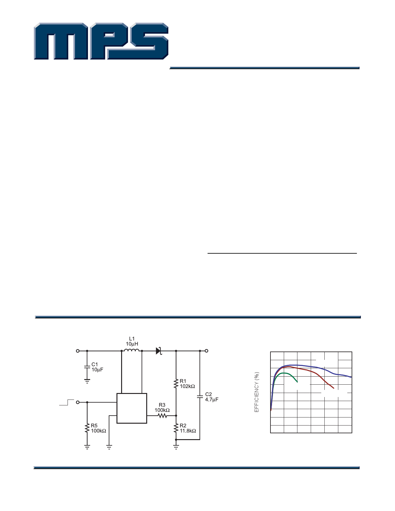
TYPICAL APPLICATION
VIN
5V
D1
OFF ON
51
4 IN
EN
SW
MP1540
2 GND
3
FB
VOUT
12V
200mA
MP1540_TAC01
Efficiency vs Load Current
100
95
90
VIN = 5V
85
80 VIN = 3.3V
75 VIN = 4.2V
70
65
60
55
50
0
75 150 225 300 375 450
LOAD CURRENT (mA)
MP1540_TAC_EC01
MP1540 Rev. 1.0
8/15/2005
www.MonolithicPower.com
MPS Proprietary Information. Unauthorized Photocopy and Duplication Prohibited.
© 2005 MPS. All Rights Reserved.
1
http://www.Datasheet4U.com
1 page 
TM
MP1540 – 1.3MHz, 18V STEP-UP CONVERTER
APPLICATIONS INFORMATION
COMPONENT SELECTION
Setting the Output Voltage
Set the output voltage b y selecting the resistive
voltage divider ratio. Use 11.8k Ω f or the lo w-
side resist or R2 of the voltage divider.
Determine the high-side resist or R1 by the
equation:
( )R1 =
R2 VOUT -
VFB
VFB
Where VOUT is the outp ut voltage and V FB is the
feedback voltage.
For R2 = 11.8kΩ and VFB = 1.25V, then
R1 (kΩ) = 9.44kΩ (VOUT – 1.25V).
Selecting the Input Capacitor
An input ca pacitor is re quired to su pply the AC
ripple current to the inductor, while limiting noise
at the input source. This capacitor must have low
ESR, so ceramic is the best choice.
Use an in put capacit or value of 4.7 µF or
greater. This capacit or must be placed
physically close to the I N pin . Since it redu ces
the voltage ripple seen at IN, it also reduces the
amount of EMI pa ssed back alo ng that line to
the other circuitry.
Selecting the Output Capacitor
A single 4 .7µF to 10 µF ceramic capacitor
usually provides sufficient output capacitan ce
for most application s. If larger amounts of
capacitance are desired for improved line
support an d transient response, tantalum
capacitors can be used in parallel with the
ceramic. The impedance of the ceramic capacitor
at the switching frequency is domin ated by the
capacitance, and so the output voltage ripple is
mostly inde pendent of the ESR. T he outpu t
voltage ripple VRIPPLE is calculated as:
( )VRIPPLE
=
ILOAD VOUT
VOUT × C2
− VIN
× fSW
Where VIN is the input voltage, ILOAD is the loa d
current, C2 is the ca pacitance of the output
capacitor, a nd f SW is the 1.3MHz switch ing
frequency.
Selecting the Inductor
The inducto r is re quired to force the output
voltage higher while being driven by the lower
input voltage. Choose a n inductor that does not
saturate at t he SW current limit. A good rule fo r
determining the inductance is to allow the peak-
to-peak ripple current to be appro ximately 30%-
50% of the maximum in put current. Make sure
that the peak inductor current is below 75% of
the typical current limit a t the duty cycle used to
prevent loss of regulat ion due to the current
limit variation.
Calculate the required inductance value L using
the equations:
L
=
VIN (VOUT - VIN )
VOUT × fSW × ∆I
IIN(MAX)
=
VOUT ×ILOAD(MAX)
VIN × η
∆I = (30% − )50% IIN(MAX)
Where ILOAD(MAX) is the maximum load current, ∆I
is the pe ak-to-peak in ductor r ipple current and η
is ef ficiency. For t he MP15 40, 4. 7µH is
recommended fo r in put vo ltages less than 3. 3V
and 10µH for inputs greater than 3.3V.
Selecting the Diode
The output rectifier diode supplies current to the
inductor when the internal MOSFET is off. To
reduce losses due to diode forward voltage and
recovery time, use a Schottky diode. Choose a
diode whose maximum reverse voltage rating is
greater than the maximum output voltage. It is
recommended to choose the MBR0520 for most
applications. This diode is used for load currents
less than 500mA. If the average current is more
than 500mA the Microsemi UPS5817 is a good
choice.
MP1540 Rev. 1.0
8/15/2005
www.MonolithicPower.com
MPS Proprietary Information. Unauthorized Photocopy and Duplication Prohibited.
© 2005 MPS. All Rights Reserved.
5
5 Page | ||
| Páginas | Total 8 Páginas | |
| PDF Descargar | [ Datasheet MP1540.PDF ] | |
Hoja de datos destacado
| Número de pieza | Descripción | Fabricantes |
| MP154 | (MP151 - MP1510) 15 Amp Single Phase Bridge Rectifier 50 to 1000 Volts | Micro Commercial Components |
| MP154 | (MP151 - MP1510) SINGLE-PHASE GLASS PASSIVATED SILICON BRIDGE RECTIFIER | Rectron Semiconductor |
| MP154 | Diode ( Rectifier ) | American Microsemiconductor |
| MP1540 | 18V Step-Up Converter | MPS |
| Número de pieza | Descripción | Fabricantes |
| SLA6805M | High Voltage 3 phase Motor Driver IC. |
Sanken |
| SDC1742 | 12- and 14-Bit Hybrid Synchro / Resolver-to-Digital Converters. |
Analog Devices |
|
DataSheet.es es una pagina web que funciona como un repositorio de manuales o hoja de datos de muchos de los productos más populares, |
| DataSheet.es | 2020 | Privacy Policy | Contacto | Buscar |