|
|
|
PDF BD9420F Data sheet ( Hoja de datos )
| Número de pieza | BD9420F | |
| Descripción | LED Drivers | |
| Fabricantes | ROHM Semiconductor | |
| Logotipo | ||
Hay una vista previa y un enlace de descarga de BD9420F (archivo pdf) en la parte inferior de esta página. Total 30 Páginas | ||
|
No Preview Available !
Datasheet
LED Drivers for LCD Backlights
White LED Driver for large LCD Panels
(DCDC Converter Type)
BD9420F
General Description
BD9420F is high efficiency driver for white LED. This is
designed for large sized LCD. BD9420F is built-in
DCDC converter that supply appropriate voltage for
light source.
BD9420F is also built-in protection function for
abnormal state such as OVP: over voltage protection,
OCP: over current limit protection of DCDC, SCP: short
circuit protection, open detection of LED string.
Thus this is used for conditions of large output voltage
and load conditions.
Features
6ch LED constant current driver(External PNP Tr
Type)
Maximum LED setting current 500mA(VREF Pin
setting)
±2% LED current accuracy(VREF=0.9V setting)
Built-in DC/DC converter
Analog Dimming(Linear) function
Built-in PWM-independent soft start circuit
LED protection function(OPEN/SHORT
protection)[PWM-independent Type]
Individual detection and individual LED OFF for both
OPEN and SHORT circuit
VOUT Over Voltage Protection(OVP) and reduced
voltage protection(SCP) circuit
Built-in under voltage lockout function(UVLO) and
over voltage protection(OVP)
Built-in VOUT discharge circuit while shutdown
Key Specifications
VCC Supply Voltage Range:
9.0V to 35.0V
DCDC Oscillation Frequency: 150kHz(RT=100kΩ)
Operation Circuit Current:
5mA(Typ)
Operating Temperature Range: -40°C to +85°C
Applications
LED driver for TV, Monitor and LCD Back Light
Package
SOP28
W(Typ) x D(Typ) x H(Max)
18.50mm x 9.90mm x 2.41mm
Pin Pitch 1.27mm
Figure 1. SOP28
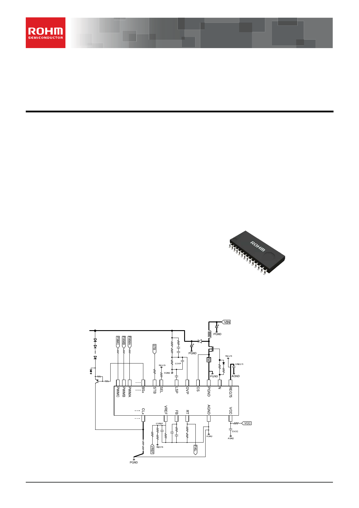
Typical Application Circuit
Figure 2. Typical Application Circuit
〇Product structure : Silicon monolithic integrated circuit 〇This product has no designed protection against radioactive rays
.www.rohm.com
© 2013 ROHM Co., Ltd. All rights reserved.
TSZ22111 • 14 • 001
1/28
TSZ02201-0F1F0C100300-1-2
31.Jan.2014 Rev.002
http://www.Datasheet4U.com
1 page 
BD9420F
Pin Descriptions
Pin No.
1
2
3
4
5
6
7
8
9
10
11
12
13
14
15
16
17
18
19
20
21
22
23
24
25
26
27
28
Pin Name
REG75
N
PGND
CS
SEL
FB
LSP
VREF
BS1
BS2
BS3
BS4
BS5
BS6
CL6
CL5
CL4
CL3
CL2
CL1
PWMC
PWMB
PWMA
OVP
RT
AGND
STB
VCC
Function
7.5V regulator output for N output pin
DC/DC switching output pin
Power GND
DCDC external NMOS current monitor pin
PWM select pin
DCDC phase-compensation pin
LED short voltage setting pin
LED voltage setting pin
PNP Tr Base connecting pin1
PNP Tr Base connecting pin2
PNP Tr Base connecting pin3
PNP Tr Base connecting pin4
PNP Tr Base connecting pin5
PNP Tr Base connecting pin6
PNP Tr collector ・current detection pin6
PNP Tr collector ・current detection pin5
PNP Tr collector ・current detection pin4
PNP Tr collector ・current detection pin3
PNP Tr collector ・current detection pin2
PNP Tr collector ・current detection pin1
Dimming signal input pin C
Dimming signal input pin B
Dimming signal input pin A
Overvoltage protection detection pin
DCDC frequency setting resistor connection pin
Analog GND
Enable pin
Power supply pin
Datasheet
www.rohm.com
© 2013 ROHM Co., Ltd. All rights reserved.
TSZ22111 • 15 • 001
5/28
TSZ02201-0F1F0C100300-1-2
31.Jan.2014 Rev.002
http://www.Datasheet4U.com
5 Page 
BD9420F
Datasheet
●LED current setting (VREF pin, CLx pin)
Please decide VREF pin input voltage first. When Analog dimming is performed,
please be noted that VREF pin input voltage range is (0.6V ~ 3.0V), and decide the
input voltage in normal operation. Basically, if VREF pin voltage is high, it will cause
power dissipation of external PNP Tr become high, so it is preferred to set the VREF pin
voltage lower.
Later, VREF=0.9V will be set as basic. For example if you create 0.9V from REG75, it
is possible to use resistive divider by setting 88kohm and 12kohm.
The LED current detection is performed by CLx pin. CLx pin is controlled so that the
voltage of 1/3V(typ.) of VREF voltage. If VREF=0.9V, CLx=0.3V to control external PNP
Tr. Therefore, if 「RCL」 is set as a resistance which between CLx pin and GND, and
VREF pin voltage is set as 「VVREF」, LED current 「ILED」can be calculated as below.
RCL
[ohm]
VVREF [V ]
I LED [ A] 3
For current setting, set at each channel. For this reason, in 1ch~3ch and 4ch~6ch, it
is possible to change current by setting 「RCL」value.
●DCDC operation frequency setting (RT Pin)
The operation frequency of DCDC output is set by resistance which connected to RT pin.
○The relationship between operation and RT resistance (ideal)
RRT
15000
fSW [kHz]
[k]
Here, fsw=DCDC converter oscillation frequency[kHz]
Above is an ideal equation which do not putted with correction terms.
For accurate frequency setting, please confirm on the real system.
But the frequency setting range is 100kHz~800kHz.
【Setting Example】
If DCDC frequency is set to be 200kHz, RRT as below:
RRT
15000 15000 75
f sw[kHz] 200[kHz]
[k]
www.rohm.com
© 2013 ROHM Co., Ltd. All rights reserved.
TSZ22111 • 15 • 001
11/28
TSZ02201-0F1F0C100300-1-2
31.Jan.2014 Rev.002
http://www.Datasheet4U.com
11 Page | ||
| Páginas | Total 30 Páginas | |
| PDF Descargar | [ Datasheet BD9420F.PDF ] | |
Hoja de datos destacado
| Número de pieza | Descripción | Fabricantes |
| BD9420F | LED Drivers | ROHM Semiconductor |
| Número de pieza | Descripción | Fabricantes |
| SLA6805M | High Voltage 3 phase Motor Driver IC. |
Sanken |
| SDC1742 | 12- and 14-Bit Hybrid Synchro / Resolver-to-Digital Converters. |
Analog Devices |
|
DataSheet.es es una pagina web que funciona como un repositorio de manuales o hoja de datos de muchos de los productos más populares, |
| DataSheet.es | 2020 | Privacy Policy | Contacto | Buscar |