|
|
|
PDF IRFHM8326PBF Data sheet ( Hoja de datos )
| Número de pieza | IRFHM8326PBF | |
| Descripción | Power MOSFET ( Transistor ) | |
| Fabricantes | International Rectifier | |
| Logotipo | ||
Hay una vista previa y un enlace de descarga de IRFHM8326PBF (archivo pdf) en la parte inferior de esta página. Total 8 Páginas | ||
|
No Preview Available !
VDSS
VGS max
RDS(on) max
(@ VGS = 10V)
(@ VGS = 4.5V)
Qg (typical)
ID
(@TC (Bottom) = 25°C)
30
±20
4.7
6.7
20
70
V
V
m
nC
A
Applications
Charge and Discharge Switch for Notebook PC Battery Application
System/Load Switch
Synchronous MOSFET for Buck Converters
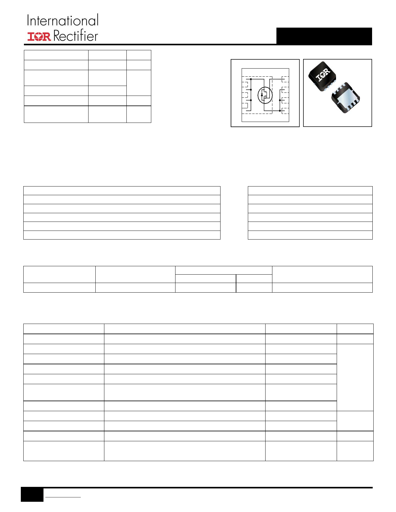
IRFHM8326PbF
HEXFET® Power MOSFET
Top View
D5
D6
4G
3S
G
SS
S
D7
D8
2S
1S
D
D
D
D
D
PQFN 3.3X3.3 mm
Features
Low Thermal Resistance to PCB (<3.4°C/W)
Low Profile (<1.05 mm)
Industry-Standard Pinout
Compatible with Existing Surface Mount Techniques
RoHS Compliant Containing no Lead, no Bromide and no Halogen
MSL1, Consumer Qualification
Benefits
Enable better thermal dissipation
Increased Power Density
results in Multi-Vendor Compatibility
Easier Manufacturing
Environmentally Friendlier
Increased Reliability
Base part number
IRFHM8326PbF
Package Type
PQFN 3.3 mm x 3.3 mm
Standard Pack
Form
Quantity
Tape and Reel
4000
Orderable Part Number
IRFHM8326TRPbF
Absolute Maximum Ratings
VGS
ID @ TA = 25°C
ID @ TA = 70°C
ID @ TC(Bottom) = 25°C
ID @ TC(Bottom) = 100°C
ID @ TC = 25°C
IDM
PD @TA = 25°C
PD @TC(Bottom) = 25°C
TJ
TSTG
Parameter
Gate-to-Source Voltage
Continuous Drain Current, VGS @ 10V
Continuous Drain Current, VGS @ 10V
Continuous Drain Current, VGS @ 10V
Continuous Drain Current, VGS @ 10V
Continuous Drain Current, VGS @ 10V (Source Bonding
Technology Limited)
Pulsed Drain Current
Power Dissipation
Power Dissipation
Linear Derating Factor
Operating Junction and
Storage Temperature Range
Notes through are on page 8
1 www.irf.com © 2013 International Rectifier
Max.
± 20
19
15
70
44
25
278
2.8
37
0.023
-55 to + 150
Units
V
A
W
W/°C
°C
March 14, 2013
Free Datasheet http://www.Datasheet4U.com
1 page 
9.0
ID = 20A
8.0
7.0
6.0 TJ = 125°C
5.0
4.0 TJ = 25°C
3.0
2
4 6 8 10 12 14 16 18 20
VGS, Gate -to -Source Voltage (V)
Fig 12. On– Resistance vs. Gate Voltage
100
10
IRFHM8326PbF
250
ID
TOP 4.7A
200 9.8A
BOTTOM 20A
150
100
50
0
25 50 75 100 125 150
Starting TJ , Junction Temperature (°C)
Fig 13. Maximum Avalanche Energy vs. Drain Current
Allowed avalanche Current vs avalanche
pulsewidth, tav, assuming Tj = 125°C and
Tstart =25°C (Single Pulse)
1
Allowed avalanche Current vs avalanche
pulsewidth, tav, assuming j = 25°C and
Tstart = 125°C.
0.1
1.0E-06
1.0E-05
1.0E-04
tav (sec)
1.0E-03
1.0E-02
Fig 14. Typical Avalanche Current vs. Pulsewidth
1.0E-01
5 www.irf.com © 2013 International Rectifier
March 14, 2013
Free Datasheet http://www.Datasheet4U.com
5 Page | ||
| Páginas | Total 8 Páginas | |
| PDF Descargar | [ Datasheet IRFHM8326PBF.PDF ] | |
Hoja de datos destacado
| Número de pieza | Descripción | Fabricantes |
| IRFHM8326PBF | Power MOSFET ( Transistor ) | International Rectifier |
| Número de pieza | Descripción | Fabricantes |
| SLA6805M | High Voltage 3 phase Motor Driver IC. |
Sanken |
| SDC1742 | 12- and 14-Bit Hybrid Synchro / Resolver-to-Digital Converters. |
Analog Devices |
|
DataSheet.es es una pagina web que funciona como un repositorio de manuales o hoja de datos de muchos de los productos más populares, |
| DataSheet.es | 2020 | Privacy Policy | Contacto | Buscar |