|
|
|
PDF IRF7665S2TRPBF Data sheet ( Hoja de datos )
| Número de pieza | IRF7665S2TRPBF | |
| Descripción | Digital Audio MOSFET | |
| Fabricantes | International Rectifier | |
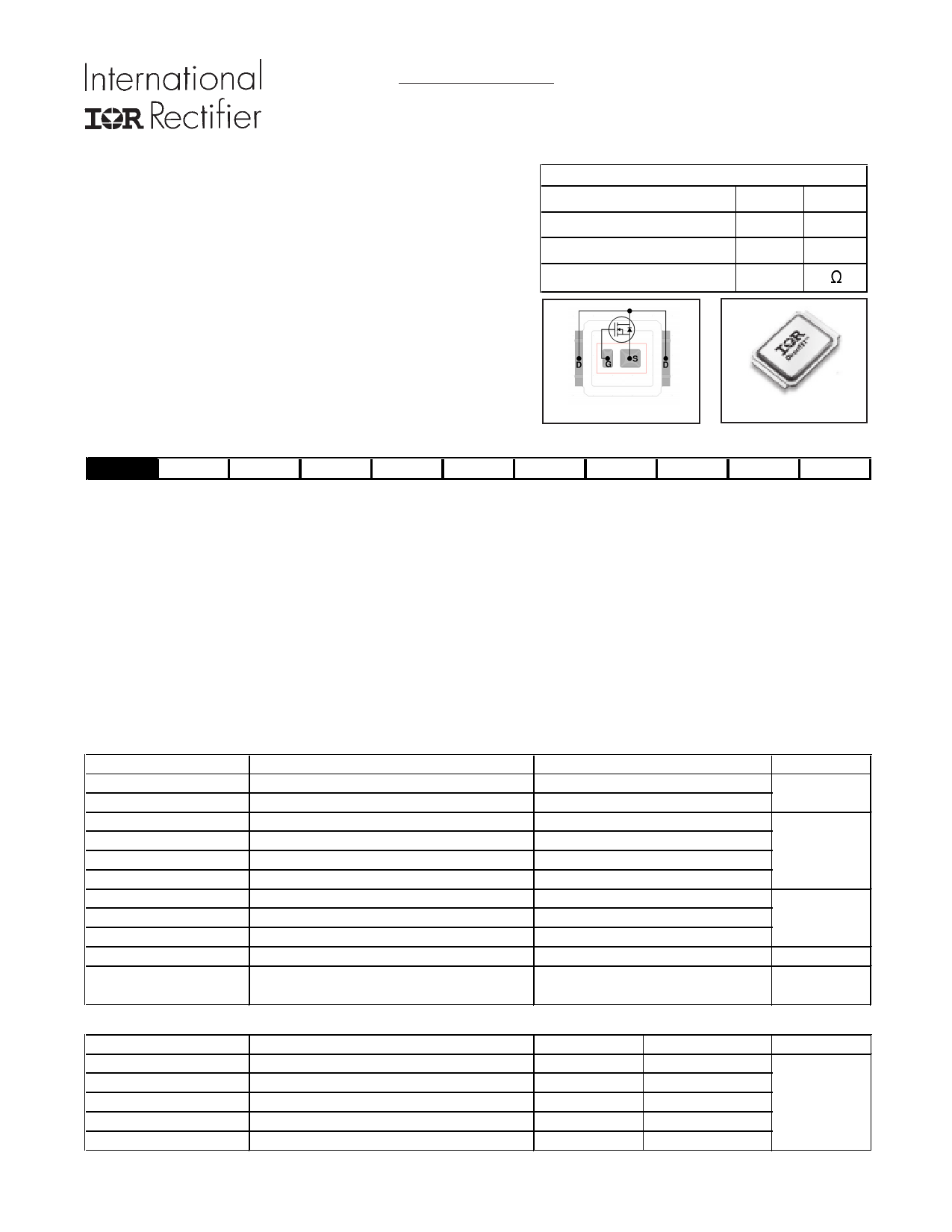
| Logotipo | ||
Hay una vista previa y un enlace de descarga de IRF7665S2TRPBF (archivo pdf) en la parte inferior de esta página. Total 9 Páginas | ||
|
No Preview Available !
DIGITAL AUDIO MOSFET
PD - 96239
IRF7665S2TRPbF
IRF7665S2TR1PbF
Features
• Key parameters optimized for Class-D audio amplifier
applications
• Low RDS(on) for improved efficiency
• Low Qg for better THD and improved efficiency
• Low Qrr for better THD and lower EMI
• Low package stray inductance for reduced ringing and lower
EMI
• Can deliver up to 100W per channel into 8Ω with no heatsink
• Dual sided cooling compatible
· Compatible with existing surface mount technologies
· RoHS compliant containing no lead or bromide
· Lead-Free (Qualified up to 260°C Reflow)
· Industrial Qualified
Key Parameters
VDS 100
RDS(on) typ. @ VGS = 10V
Qg typ.
RG(int) typ.
51
8.3
3.5
V
m:
nC
SB DirectFET ISOMETRIC
Applicable DirectFET Outline and Substrate Outline (see p. 6, 7 for details)
SB SC
M2 M4
L4 L6 L8
Description
This Digital Audio MOSFET is specifically designed for Class-D audio amplifier applications. This MOSFET utilizes the
latest processing techniques to achieve low on-resistance per silicon area. Furthermore, gate charge, body-diode reverse
recovery and internal gate resistance are optimized to improve key Class-D audio amplifier performance factors such as
efficiency, THD, and EMI.
The IRF7665S2TR/TR1PbF device utilizes DirectFETTM packaging technology. DirectFETTM packaging technology offers lower
parasitic inductance and resistance when compared to conventional wirebonded SOIC packaging. Lower inductance im-
proves EMI performance by reducing the voltage ringing that accompanies fast current transients. The DirectFETTM package is
compatible with existing layout geometries used in power applications, PCB assembly equipment and vapor phase, infra-red
or convection soldering techniques, when application note AN-1035 is followed regarding the manufacturing method and
processes. The DirectFETTM package also allows dual sided cooling to maximize thermal transfer in power systems, improving
thermal resistance and power dissipation. These features combine to make this MOSFET a highly efficient, robust and reliable
device for Class-D audio amplifier applications.
Absolute Maximum Ratings
Parameter
VDS Drain-to-Source Voltage
VGS Gate-to-Source Voltage
ID @ TC = 25°C
ID @ TC = 100°C
ID @ TA = 25°C
IDM
Continuous Drain Current, VGS @ 10V
Continuous Drain Current, VGS @ 10V
Continuous Drain Current, VGS @ 10V
Pulsed Drain Current
PD @TC = 25°C
PD @TC = 100°C
PD @TA = 25°C
TJ
TSTG
Maximum Power Dissipation
jPower Dissipation
jPower Dissipation
jÃLinear Derating Factor
Operating Junction and
Storage Temperature Range
Thermal Resistance
RθJA
RθJA
RθJA
RθJ-Can
RθJ-PCB
Parameter
eJunction-to-Ambient
hJunction-to-Ambient
iJunction-to-Ambient
jkJunction-to-Can
Junction-to-PCB Mounted
Notes through are on page 2
www.irf.com
Max.
100
± 20
14.4
10.2
4.1
58
30
15
2.4
0.2
-55 to + 175
Typ.
–––
12.5
20
–––
1.4
Max.
63
–––
–––
5.0
–––
Units
V
A
W
W/°C
°C
Units
°C/W
1
07/02/09
Free Datasheet http://www.Datasheet4U.com
1 page 
320
Vgs = 10V
280
240
200
160 TJ = 125°C
120
TJ = 25°C
80
40
0
10 20 30
ID, Drain Current (A)
40
Fig 12. On-Resistance vs. Gate Voltage
15V
VDS
L
DRIVER
RG
2V0GVS
tp
D.U.T
IAS
0.01Ω
+
-
VDD
A
Fig 15a. Unclamped Inductive Test Circuit
V(BR)DSS
tp
IRF7665S2TR/TR1PbF
140
ID = 8.9A
120
100
TJ = 125°C
80
60 TJ = 25°C
40
6 7 8 9 10 11 12 13 14 15
VGS, Gate -to -Source Voltage (V)
Fig 13. On-Resistance vs. Drain Current
160
140
TOP
ID
1.64A
120
3.04A
BOTTOM 8.90A
100
80
60
40
20
0
25 50 75 100 125 150 175
Starting TJ , Junction Temperature (°C)
IAS
Fig 15b. Unclamped Inductive Waveforms
VDS
RD
VGS
RG
D.U.T.
+
-
VDD
10V
Pulse Width ≤ 1 µs
Duty Factor ≤ 0.1 %
Fig 16a. Switching Time Test Circuit
www.irf.com
Fig 14. Maximum Avalanche Energy vs. Drain Current
VDS
90%
10%
VGS
td(on) tr
td(off) tf
Fig 16b. Switching Time Waveforms
5
Free Datasheet http://www.Datasheet4U.com
5 Page | ||
| Páginas | Total 9 Páginas | |
| PDF Descargar | [ Datasheet IRF7665S2TRPBF.PDF ] | |
Hoja de datos destacado
| Número de pieza | Descripción | Fabricantes |
| IRF7665S2TRPbF | DIGITAL AUDIO MOSFET | IRF |
| IRF7665S2TRPBF | Digital Audio MOSFET | International Rectifier |
| Número de pieza | Descripción | Fabricantes |
| SLA6805M | High Voltage 3 phase Motor Driver IC. |
Sanken |
| SDC1742 | 12- and 14-Bit Hybrid Synchro / Resolver-to-Digital Converters. |
Analog Devices |
|
DataSheet.es es una pagina web que funciona como un repositorio de manuales o hoja de datos de muchos de los productos más populares, |
| DataSheet.es | 2020 | Privacy Policy | Contacto | Buscar |