|
|
|
PDF CMF10120D Data sheet ( Hoja de datos )
| Número de pieza | CMF10120D | |
| Descripción | Silicon Carbide Power MOSFET | |
| Fabricantes | Cree | |
| Logotipo | ||
Hay una vista previa y un enlace de descarga de CMF10120D (archivo pdf) en la parte inferior de esta página. Total 8 Páginas | ||
|
No Preview Available !
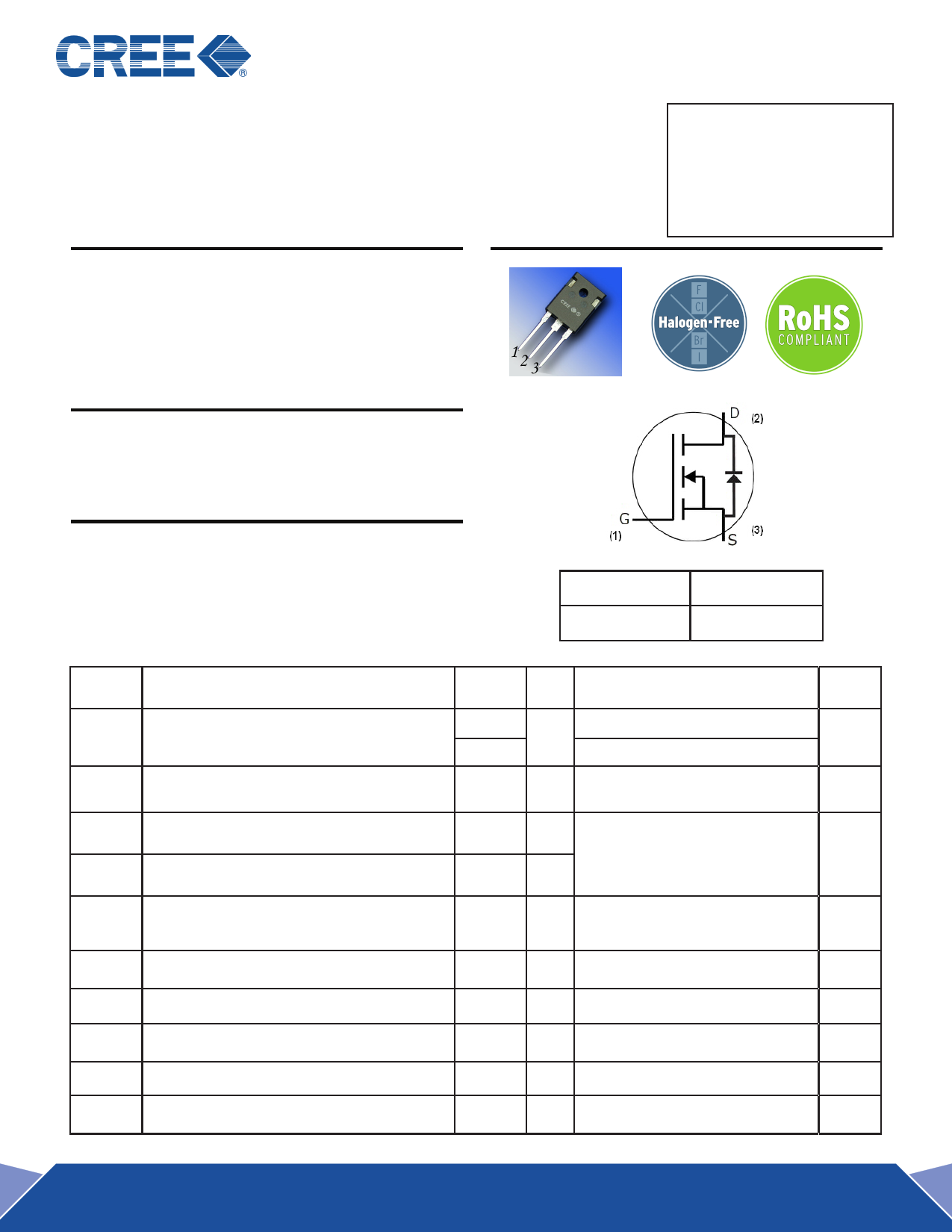
CMF10120D-Silicon Carbide Power MOSFET
Z-F MOSFETeTTM
VDS
= 1200 V
N-Channel Enhancement Mode ID (MAX) = 2 4 A
RDS(on)
= 160mΩ
Features
Package
• High Speed Switching with Low Capacitances
•
•
High Blocking Voltage with Low RDS(on)
Easy to Parallel and Simple to Drive
• Avalanche Ruggedness
• Resistant to Latch-Up
• Halogen Free, RoHS Compliant
Benefits
TO-247-3
• Higher System Efficiency
• Reduced Cooling Requirements
• Increased System Switching Frequency
Applications
• Solar Inverters
• High Voltage DC/DC Converters
• Motor Drives
• Switch Mode Power Supplies
Maximum Ratings (TC = 25˚C unless otherwise specified)
Part Number
CMF10120D
Package
TO-247-3
Symbol
Parameter
Value Unit
Test Conditions
Note
ID Continuous Drain Current
IDpulse Pulsed Drain Current
EAS Single Pulse Avalanche Energy
EAR Repetitive Avalanche Energy
24 A VGS@20V, TC = 25˚C
13 VGS@20V, TC = 100˚C
Fig. 10
49 A Pulse width tP limited by Tjmax
TC = 25˚C
1.2 J ID = 10A, VDD = 50 V,
L = 20 mH
0.8 J tAR limited by Tjmax
Fig. 15
IAR Repetitive Avalanche Current
10 A ID = 10A, VDD = 50 V, L = 15 mH
tAR limited by Tjmax
VGS Gate Source Voltage
-5/+25 V
Ptot Power Dissipation
TJ , Tstg Operating Junction and Storage Temperature
TL Solder Temperature
Md Mounting Torque
134
-55 to
+135
260
1
8.8
W TC=25˚C
˚C
Fig. 9
˚C 1.6mm (0.063”) from case for 10s
Nm
lbf-in
M3 or 6-32 screw
1 CMF10120D Rev. A
Free Datasheet http://www.nDatasheet.com
1 page 
Typical Performance
10000
1000
100
10
Ciss
Coss
Crss
10000
1000
100
10
Ciss
Coss
Crss
1
0
40
35
30
25
20
15
10
5
0
0
20 40 60 80 100 120 140 160 180 200
VDS (V)
1
0 100 200 300 400 500 600 700 800
VDS (V)
Figure 13A and 13B. Typical Capacitances vs. Drain Voltage at VGS = 0V and f = 1 MHz
100 200 300 400 500 600 700
VDS (V)
Figure 14. Typical COSS Stored Energy
800
11
10
9
8
7
6
5
4
3
2
1
0
0
VGS = 0/20V
VDD = 50V
L = 20 mH
EAS = 1.2 J
ID
0.001
0.002
0.003
Time (sec)
0.004
0.005
2500
VDS
2000
1500
1000
500
0
0.006
Figure 15. Typical Unclamped Inductive Switching
Waveforms Showing Avalanche Capability
80
70 VGS = 0/20V
VDD = 400V
60
RL = 40 Ω
ID = 10 A
TA = 25oC
50
40
30
20
10
tD(off)v
trv
tfv
tD(on)v
90
80 VGS = 0/20V
VDD =800V
70 RL = 80 Ω
ID = 10 A
60 TA = 25oC
50
40
30
20
10
tD(off)v
trv
tfv
tD(on)v
0
0 5 10 15 20 25
External Gate Resistor (Ω)
0
0 5 10 15 20 25
External Gate Resistor (Ω)
Figure 16. Resistive Switching Times vs.
Figure 17. Resistive Switching Times vs.
External RG at VDD = 400V, ID = 10A
External RG at VDD = 800V, ID = 10A
5 CMF10120D Rev. A
Free Datasheet http://www.nDatasheet.com
5 Page | ||
| Páginas | Total 8 Páginas | |
| PDF Descargar | [ Datasheet CMF10120D.PDF ] | |
Hoja de datos destacado
| Número de pieza | Descripción | Fabricantes |
| CMF10120D | Silicon Carbide Power MOSFET | Cree |
| Número de pieza | Descripción | Fabricantes |
| SLA6805M | High Voltage 3 phase Motor Driver IC. |
Sanken |
| SDC1742 | 12- and 14-Bit Hybrid Synchro / Resolver-to-Digital Converters. |
Analog Devices |
|
DataSheet.es es una pagina web que funciona como un repositorio de manuales o hoja de datos de muchos de los productos más populares, |
| DataSheet.es | 2020 | Privacy Policy | Contacto | Buscar |