|
|
|
PDF LT4320 Data sheet ( Hoja de datos )
| Número de pieza | LT4320 | |
| Descripción | Ideal Diode Bridge Controller | |
| Fabricantes | Linear Technology | |
| Logotipo | ||
Hay una vista previa y un enlace de descarga de LT4320 (archivo pdf) en la parte inferior de esta página. Total 14 Páginas | ||
|
No Preview Available !
Features
n Maximizes Power Efficiency
n Eliminates Thermal Design Problems
n DC to 600Hz
n 9V to 72V Operating Voltage Range
n IQ = 1.5mA (Typical)
n Maximizes Available Voltage
n Available in 8-Lead (3mm × 3mm) DFN, 12-Lead
MSOP and 8-Lead PDIP Packages
Applications
n Security Cameras
n Terrestrial or Airborne Power Distribution Systems
n Power-over-Ethernet Powered Device with a
Secondary Input
n Polarity-Agnostic Power Input
n Diode Bridge Replacement
L, LT, LTC, LTM, Linear Technology and the Linear logo are registered trademarks of Linear
Technology Corporation. All other trademarks are the property of their respective owners.
Patent pending.
LT4320/LT4320-1
Ideal Diode Bridge
Controller
Description
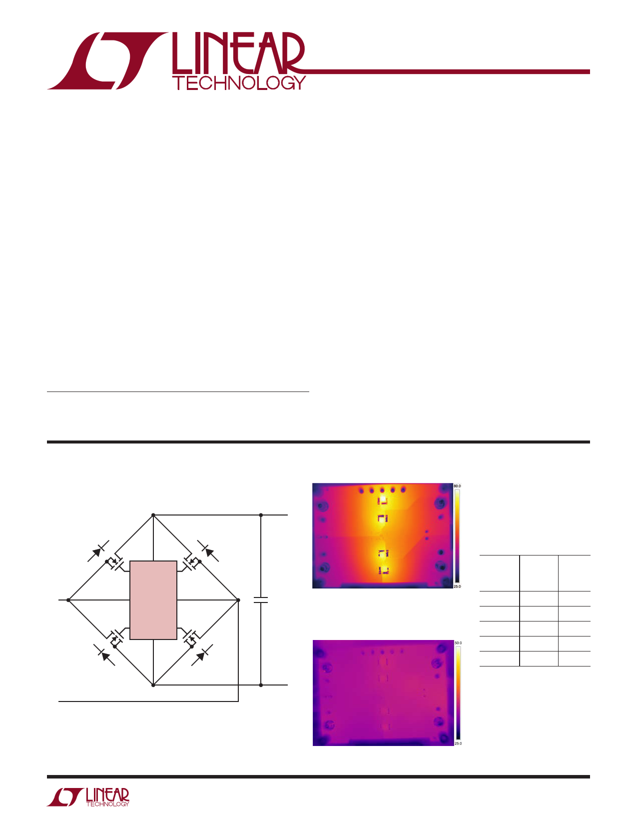
The LT®4320/LT4320-1 are ideal diode bridge controllers
that drive four N-channel MOSFETs, supporting voltage
rectification from DC to 600Hz typical. By maximizing
available voltage and reducing power dissipation (see
thermograph comparison below), the ideal diode bridge
simplifies power supply design and reduces power supply
cost, especially in low voltage applications.
An ideal diode bridge also eliminates thermal design
problems, costly heat sinks, and greatly reduces PC board
area. The LT4320’s internal charge pump supports an all-
NMOS design, which eliminates larger and more costly
PMOS switches. If the power source fails or is shorted, a
fast turn-off minimizes reverse current transients.
The LT4320 is designed for DC to 60Hz typical voltage
rectification, while the LT4320-1 is designed for DC to
600Hz typical voltage rectification. Higher frequencies of
operation are possible depending on MOSFET size and
operating load current.
Typical Application
Thermograph of Passive Diode Bridge
~
INPUT
DC TO 600Hz (TYP)
~
OUTP
TG1 TG2
LT4320
IN1 IN2
BG2 BG1
OUTN
+
OUTPUT
9V TO 72V
4320 TA01a
–
SBM1040 (×4)
4320 TA01b
Thermograph of LT4320
Driving Four MOSFETs
Temperature Rise (°C)
DIODE
CURRENT MOSFET SBM
(A) 2.5mΩ 1040
2 0.6 15
4 3.5 32
6 6.7 49
8 11 66
10 16 84
DC Input, On Same PCB
LT4320+2.5mΩ FET (×4)
4320 TA01c
CONDITIONS: 24V ACIN, 9.75A DC LOAD ON SAME PCB
For more information www.linear.com/LT4320
4320fa
1
Free Datasheet http://www.nDatasheet.com
1 page 
LT4320/LT4320-1
Pin Functions (DFN, PDIP/MSOP)
IN2 (Pin 1/Pin 1): Bridge Rectifier Input. IN2 connects to
the external NMOS transistors MTG2 source, MBG1 drain
and the power input.
TG2 (Pin 2/Pin 2): Topside Gate Driver Output. TG2 pin
drives MTG2 gate.
BG2 (Pin 3/Pin 5): Bottom-Side Gate Driver Output. BG2
pin drives MBG2 gate.
BG1 (Pin 4/Pin 6): Bottom-Side Gate Driver Output. BG1
pin drives MBG1 gate.
OUTN (Pin 5/Pin 7): OUTN is the rectified negative output
voltage, and connects to the sources of MBG1 and MBG2.
OUTP (Pin 6/Pin 9): OUTP is the rectified positive output
voltage that powers the LT4320 and connects to the drains
of MTG1 and MTG2.
TG1 (Pin 7/Pin 11): Topside Gate Driver Output. TG1 pin
drives MTG1 gate.
IN1 (Pin 8/Pin 12): Bridge Rectifier Input. IN1 connects
to the external NMOS transistors MTG1 source, MBG2
drain, and the power input.
NC (Pins 3, 4, 8, 10, MSOP Only): No Connections. Not
internally connected.
Exposed Pad (Pin 9/Pin 13): Exposed Pad, DFN and MSOP.
Must be connected to OUTN.
Block Diagram
~
MTG2
MTG1
TG2 TG1 LT4320
+
IN1 OUTP
CONTROL
IN2
OUTN
BG2 BG1
~ MBG2
–
MBG1
LT4320 BD
For more information www.linear.com/LT4320
4320fa
5
Free Datasheet http://www.nDatasheet.com
5 Page 
LT4320/LT4320-1
Package Description
Please refer to http://www.linear.com/designtools/packaging/ for the most recent package drawings.
2.845 ±0.102
(.112 ±.004)
MSE Package
12-Lead Plastic MSOP, Exposed Die Pad
(Reference LTC DWG # 05-08-1666 Rev G)
0.889 ±0.127
(.035 ±.005)
BOTTOM VIEW OF
EXPOSED PAD OPTION
2.845 ±0.102
(.112 ±.004)
16
0.35
REF
5.10
(.201)
MIN
1.651 ±0.102 3.20 – 3.45
(.065 ±.004) (.126 – .136)
0.42 ±0.038
(.0165 ±.0015)
TYP
0.65
(.0256)
BSC
RECOMMENDED SOLDER PAD LAYOUT
0.254
(.010)
GAUGE PLANE
DETAIL “A”
0° – 6° TYP
4.90 ±0.152
(.193 ±.006)
1.651 ±0.102
(.065 ±.004)
0.12 REF
DETAIL “B”
CORNER TAIL IS PART OF
DETAIL “B” THE LEADFRAME FEATURE.
12 7
4.039 ±0.102
FOR REFERENCE ONLY
NO MEASUREMENT PURPOSE
(.159 ±.004)
(NOTE 3)
0.406 ±0.076
12 11 10 9 8 7
(.016 ±.003)
REF
3.00 ±0.102
(.118 ±.004)
(NOTE 4)
0.18
(.007)
DETAIL “A”
0.53 ±0.152
(.021 ±.006)
1.10
(.043)
MAX
1 23 456
0.86
(.034)
REF
SEATING
PLANE 0.22 – 0.38
0.1016 ±0.0508
NOTE:
(.009 – .015)
TYP
0.650
(.0256)
(.004 ±.002)
MSOP (MSE12) 0213 REV G
1. DIMENSIONS IN MILLIMETER/(INCH)
BSC
2. DRAWING NOT TO SCALE
3. DIMENSION DOES NOT INCLUDE MOLD FLASH, PROTRUSIONS OR GATE BURRS.
MOLD FLASH, PROTRUSIONS OR GATE BURRS SHALL NOT EXCEED 0.152mm (.006") PER SIDE
4. DIMENSION DOES NOT INCLUDE INTERLEAD FLASH OR PROTRUSIONS.
INTERLEAD FLASH OR PROTRUSIONS SHALL NOT EXCEED 0.152mm (.006") PER SIDE
5. LEAD COPLANARITY (BOTTOM OF LEADS AFTER FORMING) SHALL BE 0.102mm (.004") MAX
6. EXPOSED PAD DIMENSION DOES INCLUDE MOLD FLASH. MOLD FLASH ON E-PAD SHALL
NOT EXCEED 0.254mm (.010") PER SIDE.
For more information www.linear.com/LT4320
4320fa
11
Free Datasheet http://www.nDatasheet.com
11 Page | ||
| Páginas | Total 14 Páginas | |
| PDF Descargar | [ Datasheet LT4320.PDF ] | |
Hoja de datos destacado
| Número de pieza | Descripción | Fabricantes |
| LT4320 | Ideal Diode Bridge Controller | Linear Technology |
| LT4320-1 | Ideal Diode Bridge Controller | Linear Technology |
| LT4321 | PoE Ideal Diode Bridge Controller | Linear Technology |
| LT4321HUF | PoE Ideal Diode Bridge Controller | Linear Technology |
| Número de pieza | Descripción | Fabricantes |
| SLA6805M | High Voltage 3 phase Motor Driver IC. |
Sanken |
| SDC1742 | 12- and 14-Bit Hybrid Synchro / Resolver-to-Digital Converters. |
Analog Devices |
|
DataSheet.es es una pagina web que funciona como un repositorio de manuales o hoja de datos de muchos de los productos más populares, |
| DataSheet.es | 2020 | Privacy Policy | Contacto | Buscar |