|
|
|
PDF HI-8282ACRT Data sheet ( Hoja de datos )
| Número de pieza | HI-8282ACRT | |
| Descripción | ARINC 429 SERIAL TRANSMITTER AND DUAL RECEIVER | |
| Fabricantes | Holt Integrated Circuits | |
| Logotipo | ||
Hay una vista previa y un enlace de descarga de HI-8282ACRT (archivo pdf) en la parte inferior de esta página. Total 14 Páginas | ||
|
No Preview Available !
May 2001
HI-8282A
ARINC 429 SERIAL TRANSMITTER AND DUAL RECEIVER
GENERAL DESCRIPTION
The HI-8282A is a silicon gate CMOS device for interfacing
the ARINC 429 serial data bus to a 16-bit parallel data bus.
Two receivers and an independent transmitter are
provided. The receiver input circuitry and logic are
designed to meet the ARINC 429 specifications for loading,
level detection, timing, and protocol. The transmitter
section provides the ARINC 429 communication protocol.
Additional interface circuitry such as the Holt HI-8585,
HI-8586 or HI-3182 is required to translate the 5 volt logic
outputs to ARINC 429 drive levels.
The 16-bit parallel data bus exchanges the 32-bit ARINC
data word in two steps when either loading the transmitter
or interrogating the receivers. The data bus interfaces with
CMOS and TTL.
Timing of all the circuitry begins with the master clock input,
CLK. For ARINC 429 applications, the master clock
frequency is 1 MHz.
Each independent receiver monitors the data stream with a
sampling rate 10 times the data rate. The sampling rate is
software selectable at either 1MHz or 125KHz. The results
of a parity check are available as the 32nd ARINC bit. The
HI-8282A examines the null and data timings and will reject
erroneous patterns. For example, with a 125 KHz clock
selection, the data frequency must be between 10.4 KHz
and 15.6 KHz.
The transmitter has a First In, First Out (FIFO) memory to
store 8 ARINC words for transmission. The data rate of the
transmitter is software selectable by dividing the master
clock, CLK, by either 10 or 80. The master clock is used to
set the timing of the ARINC transmission within the required
resolution.
APPLICATIONS
! Avionics data communication
! Serial to parallel conversion
! Parallel to serial conversion
FEATURES
! ARINC specification 429 compatible
! 16-Bit parallel data bus
! Direct receiver interface to ARINC bus
! Timing control 10 times the data rate
! Selectable data clocks
! Receiver error rejection per ARINC
specification 429
! Automatic transmitter data timing
! Self test mode
! Parity functions
! Low power, single 5 volt supply
! Industrial & full military temperature ranges
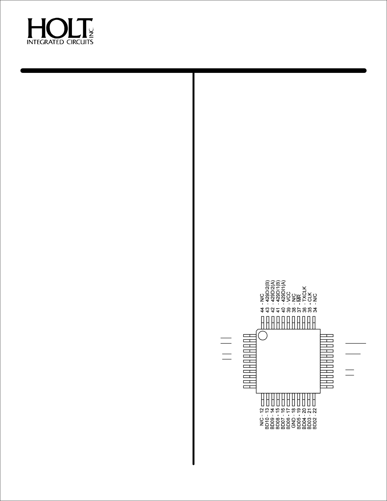
PIN CONFIGURATION (Top View)
N/C - 1
D/R1 - 2
D/R2 - 3
SEL - 4
EN1 - 5
EN2 - 6
BD15 - 7
BD14 - 8
BD13 - 9
BD12 - 10
BD11 - 11
HI-8282APQI
&
HI-8282APQT
33 - N/C
32 - N/C
31 - CWSTRX
30 - ENTX
29 - 429DO
28 - 429DO
27 - TX/R
26 - PL2
25 - PL1
24 - BD00
23 - BD01
44-Pin Plastic Quad Flat Pack (PQFP)
(See page 10 for additional Package Pin Configurations)
(DS8282A Rev. New)
HOLT INTEGRATED CIRCUITS
1
05/01
1 page 
HI-8282A
TRANSMITTER
A block diagram of the transmitter section is shown in Figure 3.
FIFO OPERATION
The FIFO is loaded sequentially by first pulsing PL1 to load byte 1
and then PL2 to load byte 2. The control logic automatically loads
the 31 bit word in the next available position of the FIFO. If TX/R,
the transmitter ready flag is high (FIFO empty), then 8 words,
each 31 bits long, may be loaded. If TX/R is low, then only the
available positions may be loaded. If all 8 positions are full, the
FIFO ignores further attempts to load data.
DATA TRANSMISSION
When ENTX goes high, enabling transmission, the FIFO
positions are incremented with the top register loading into the
data transmission shift register. Within 2.5 data clocks the first
data bit appears at either 429DO or 429DO. The 31 bits in the
data transmission shift register are presented sequentially to the
outputs in the ARINC 429 format with the following timing:
ARINC DATA BIT TIME
DATA BIT TIME
NULL BIT TIME
WORD GAP TIME
HIGH SPEED
10 Clocks
5 Clocks
5 Clocks
40 Clocks
LOW SPEED
80 Clocks
40 Clocks
40 Clocks
320 Clocks
The word counter detects when all loaded positions are
transmitted and sets the transmitter ready flag, TX/R, high.
TRANSMITTER PARITY
The parity generator counts the ONES in the 31-bit word. If the
BD12 control word bit is set low, the 32nd bit transmitted will make
parity odd. If the control bit is high the parity is even.
SELF TEST
If the BD05 control word bit is set low, 429DO or 429DO become
inputs to the receiver bypassing the interface circuitry.
SYSTEMOPERATION
The two receivers are independent of the transmitter. Therefore,
control of data exchanges are strictly at the option of the user. The
only restrictions are:
1. The received data may be overwritten if not retrieved
within one ARINC word cycle.
2. The FIFO can store 8 words maximum and ignores
attempts to load addition data if full.
3. Byte 1 of the transmitter data must be loaded first.
4. Either byte of the received data may be retrieved first.
Both bytes must be retrieved to clear the data ready flag.
5. After ENTX, transmission enable, goes high it cannot go
low until TX/R, transmitter readyflag, goes high. Otherwise,
one ARINC word is lost during transmission.
HOLT INTEGRATED CIRCUITS
5
5 Page 
HI-8282A
PART
NUMBER
HI-8282ACDI
HI-8282ACDT
HI-8282ACDM
HI-8282APJI
HI-8282APJT
HI-8282APQI
HI-8282APQT
HI-8282ACLI
HI-8282ACLT
HI-8282ACLM
HI-8282ACRI
HI-8282ACRT
PACKAGE
DESCRIPTION
40 PIN CERAMIC SIDE BRAZED DIP
40 PIN CERAMIC SIDE BRAZED DIP
40 PIN CERAMIC SIDE BRAZED DIP
44 PIN PLASTIC J LEAD
44 PIN PLASTIC J LEAD
44 PIN PLASTIC QUAD FLAT PACK
44 PIN PLASTIC QUAD FLAT PACK
44 PIN CERAMIC LEADLESS CHIP CARRIER
44 PIN CERAMIC LEADLESS CHIP CARRIER
44 PIN CERAMIC LEADLESS CHIP CARRIER
44 PIN CERQUAD
44 PIN CERQUAD
TEMPERATURE
RANGE
-40°C TO +85°C
-55°C TO +125°C
-55°C TO +125°C
-40°C TO +85°C
-55°C TO +125°C
-40°C TO +85°C
-55°C TO +125°C
-40°C TO +85°C
-55°C TO +125°C
-55°C TO +125°C
-40°C TO +85°C
-55°C TO +125°C
FLOW BURN
IN
I NO
T NO
M YES
I NO
T NO
I NO
T NO
I NO
T NO
M YES
I NO
T NO
LEAD
FINISH
GOLD
GOLD
SOLDER
SOLDER
SOLDER
SOLDER
SOLDER
GOLD
GOLD
SOLDER
SOLDER
SOLDER
HOLT INTEGRATED CIRCUITS
11
11 Page | ||
| Páginas | Total 14 Páginas | |
| PDF Descargar | [ Datasheet HI-8282ACRT.PDF ] | |
Hoja de datos destacado
| Número de pieza | Descripción | Fabricantes |
| HI-8282ACRI | ARINC 429 SERIAL TRANSMITTER AND DUAL RECEIVER | Holt Integrated Circuits |
| HI-8282ACRT | ARINC 429 SERIAL TRANSMITTER AND DUAL RECEIVER | Holt Integrated Circuits |
| Número de pieza | Descripción | Fabricantes |
| SLA6805M | High Voltage 3 phase Motor Driver IC. |
Sanken |
| SDC1742 | 12- and 14-Bit Hybrid Synchro / Resolver-to-Digital Converters. |
Analog Devices |
|
DataSheet.es es una pagina web que funciona como un repositorio de manuales o hoja de datos de muchos de los productos más populares, |
| DataSheet.es | 2020 | Privacy Policy | Contacto | Buscar |