|
|
|
PDF HI-565 Data sheet ( Hoja de datos )
| Número de pieza | HI-565 | |
| Descripción | High Speed/ Monolithic D/A Converter with Reference | |
| Fabricantes | Intersil Corporation | |
| Logotipo | ||
Hay una vista previa y un enlace de descarga de HI-565 (archivo pdf) en la parte inferior de esta página. Total 9 Páginas | ||
|
No Preview Available !
Data Sheet
HI-565A
June 1999 File Number 3109.2
High Speed, Monolithic D/A Converter
with Reference
The HI-565A is a fast, 12-bit, current output, digital-to-analog
converter. The monolithic chip includes a precision voltage
reference, thin-film R2R ladder, reference control amplifier
and twelve high speed bipolar current switches.
The Intersil dielectric isolation process provides latch free
operation while minimizing stray capacitance and leakage
currents, to produce an excellent combination of speed and
accuracy. Also, ground currents are minimized to produce a
low and constant current through the ground terminal, which
reduces error due to code dependent ground currents.
HI-565A dice are laser trimmed for a maximum integral
nonlinearity error of ±0.5 LSB at 25oC. In addition, the low
noise buried zener reference is trimmed both for absolute
value and temperature coefficient. Power dissipation is
typically 250mW, with ±15V supplies.
The HI-565A is offered in both commercial and military
grades. See Ordering Information.
Features
• 12-Bit DAC and Reference on a Single Chip
• Pin Compatible With AD565A
• Very High Speed: Settles to ±0.5 LSB in 250ns (Max)
Full Scale Switching Time 30ns (Typ)
• Guaranteed For Operation With ±12V Supplies
• Monotonicity Guaranteed Over Temperature
• Nonlinearity Guaranteed Over Temp (Max) . . . . ±0.5 LSB
• Low Gain Drift (Max, DAC Plus Ref) . . . . . . . . .25ppm/oC
• Low Power Dissipation . . . . . . . . . . . . . . . . . . . . .250mW
Applications
• CRT Displays
• High Speed A/D Converters
• Signal Reconstruction
• Waveform Synthesis
Ordering Information
PART NUMBER
HI1-565AJD-5
HI1-565AKD-5
HI1-565ASD-2
HI1-565ATD-2
HI1-565ASD/883
HI1-565ATD/883
LINEARITY (INL)
0.50 LSB
0.25 LSB
0.50 LSB
0.25 LSB
0.50 LSB
0.25 LSB
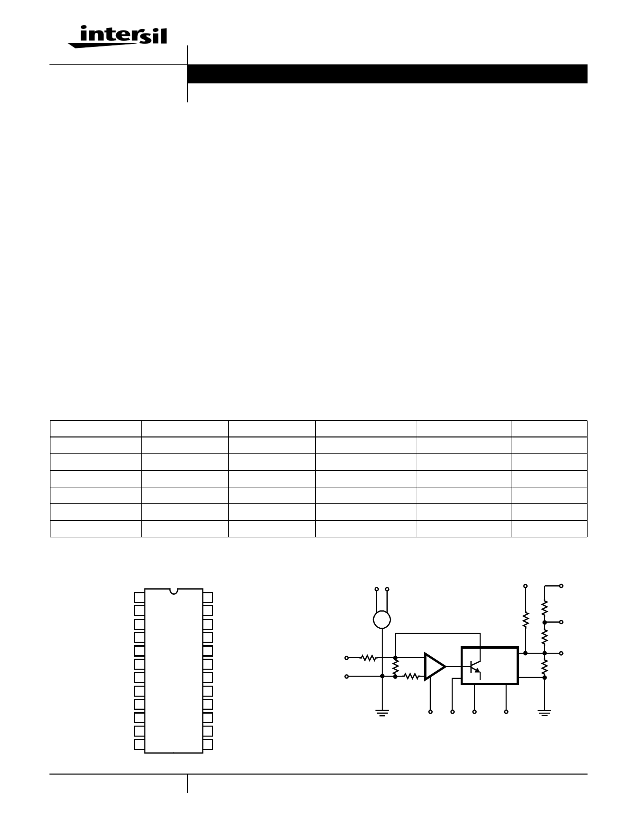
Pinout
HI-565A (SBDIP)
TOP VIEW
LINEARITY (DNL)
0.75 LSB
0.50 LSB
0.75 LSB
0.50 LSB
0.50 LSB
0.50 LSB
NC 1
NC 2
VCC 3
REF OUT (+10V) 4
REF GND 5
REF IN 6
-VEE 7
BIPOLAR R IN 8
IDAC OUT 9
10V SPAN R 10
20V SPAN R 11
POWER GND 12
24 BIT 1 (MSB) IN
23 BIT 2 IN
22 BIT 3 IN
21 BIT 4 IN
20 BIT 5 IN
19 BIT 6 IN
18 BIT 7 IN
17 BIT 8 IN
16 BIT 9 IN
15 BIT 10 IN
14 BIT 11 IN
13 BIT 12 (LSB) IN
TEMP. RANGE (oC)
0 to 75
0 to 75
-55 to 125
-55 to 125
-55 to 125
-55 to 125
PACKAGE
24 Ld SBDIP
24 Ld SBDIP
24 Ld SBDIP
24 Ld SBDIP
24 Ld SBDIP
24 Ld SBDIP
Functional Diagram
PKG. NO.
D24.6
D24.6
D24.6
D24.6
D24.6
D24.6
REF
OUT VCC
43
+
HI-565A
-
REF
IN
6 19.95K
5
IREF 0.5mA
3.5K
+
-
REF
GND
3K
7 12
8
BIP. OFF
5K
9.95K
DAC
IO
(4X IREF
X CODE)
5K
2.5K
24 . . . . . .13
11 20V
SPAN
10 10V
SPAN
9
OUT
-VEE PWR MSB
GND
LSB
1 CAUTION: These devices are sensitive to electrostatic discharge; follow proper IC Handling Procedures.
1-888-INTERSIL or 321-724-7143 | Copyright © Intersil Corporation 1999
1 page 
HI-565A
added to convert this current to a voltage. Refer to Table 2
for the voltage output case, along with Figure 1 or Figure 2.
Calibration is a two step process for each of the five output
ranges shown in Table 2. First adjust the negative full scale
(zero for unipolar ranges). This is an offset adjust which
translates the output characteristic, i.e., affects each code by
the same amount.
Next adjust positive FS. This is a gain error adjustment, which
rotates the output characteristic about the negative FS value.
For the bipolar ranges, this approach leaves an error at the
zero code, whose maximum value is the same as for integral
nonlinearity error. In general, only two values of output may
be calibrated exactly; all others must tolerate some error.
Choosing the extreme end points (plus and minus full scale)
minimizes this distributed error for all other codes.
MODE
Unipolar
(See Figure 1)
Bipolar
(See Figure 2)
OUTPUT
PRANGE
0 to +10V
0 to +5V
±10V
±5V
±2.5V
TABLE 2. OPERATING MODES AND CALIBRATION
CIRCUIT CONNECTIONS
PIN 10 TO
VO
VO
NC
VO
VO
PIN 11 TO
Pin 10
Pin 9
VO
Pin 10
Pin 9
CALIBRATION
APPLY
RESlSTOR (R) INPUT CODE
ADJUST
1.43K
All 0’s
All 1’s
R1
R2
1.1K
All 0’s
All 1’s
R1
R2
1.69K
All 0’s
All 1’s
R3
R4
1.43K
All 0’s
All 1’s
R3
R4
1.1K
All 0’s
All 1’s
R3
R4
TO SET
VO
0V
+9.99756V
0V
+4.99878V
-10V
+9.99512V
-5V
+4.99756V
-2.5V
+2.49878V
REF OUT VCC
R2
100Ω
43
+
10V
-
HI-565A
I REF
REF 6 19.95K
IN
REF 5
GND
0.5mA
3.5K
3K
+-
BIP.
OFF. 8
5K
9.95K
DAC
IO
(4 x I REF
x CODE)
5K
2.5K
CODE
INPUT
7 12 24
MSB
-VEE PWR
GND
13
LSB
11
20V SPAN
10
10V SPAN
VO
C
9
DAC
OUT
+-
R (SEE
TABLE 2)
FIGURE 1. UNIPOLAR VOLTAGE OUTPUT
100kΩ
100Ω
+15V
R1
50kΩ
-15V
5
5 Page | ||
| Páginas | Total 9 Páginas | |
| PDF Descargar | [ Datasheet HI-565.PDF ] | |
Hoja de datos destacado
| Número de pieza | Descripción | Fabricantes |
| HI-565 | High Speed/ Monolithic D/A Converter with Reference | Intersil Corporation |
| HI-565A | High Speed/ Monolithic D/A Converter with Reference | Intersil Corporation |
| HI-5680 | 12-Bit Low Cost Monolithic Digital to Analog Converter | Harris Semiconductor |
| Número de pieza | Descripción | Fabricantes |
| SLA6805M | High Voltage 3 phase Motor Driver IC. |
Sanken |
| SDC1742 | 12- and 14-Bit Hybrid Synchro / Resolver-to-Digital Converters. |
Analog Devices |
|
DataSheet.es es una pagina web que funciona como un repositorio de manuales o hoja de datos de muchos de los productos más populares, |
| DataSheet.es | 2020 | Privacy Policy | Contacto | Buscar |