|
|
|
PDF 42N03LT Data sheet ( Hoja de datos )
| Número de pieza | 42N03LT | |
| Descripción | PHB42N03LT | |
| Fabricantes | NXP Semiconductors | |
| Logotipo | ||
Hay una vista previa y un enlace de descarga de 42N03LT (archivo pdf) en la parte inferior de esta página. Total 8 Páginas | ||
|
No Preview Available !
Philips Semiconductors
TrenchMOS™ transistor
Logic level FET
Product specification
PHB42N03LT
FEATURES
• ’Trench’ technology
• Very low on-state resistance
• Fast switching
• Stable off-state characteristics
• High thermal cycling performance
• Low thermal resistance
• Surface mounting package
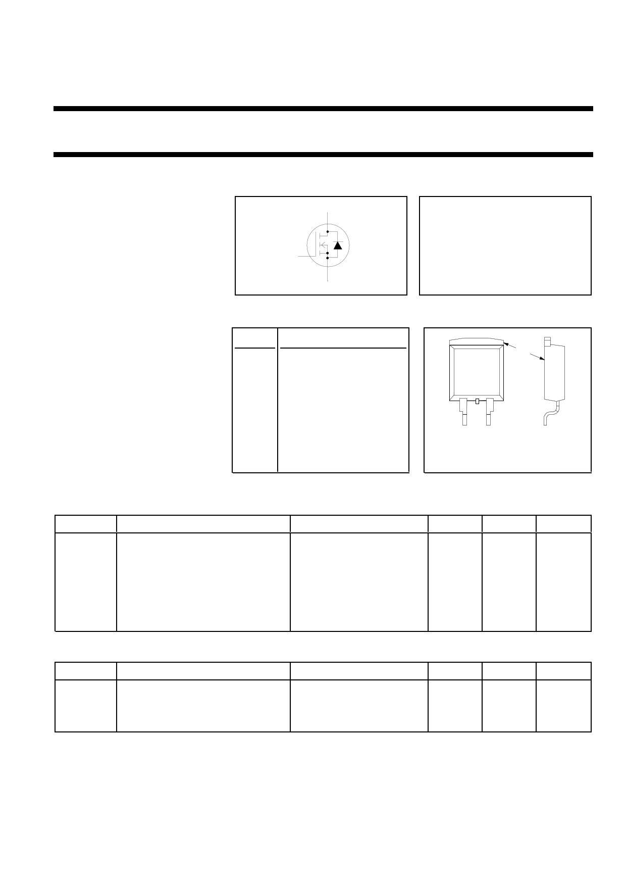
SYMBOL
g
d
s
QUICK REFERENCE DATA
VDSS = 30 V
ID = 42 A
RDS(ON) ≤ 26 mΩ (VGS = 5 V)
RDS(ON) ≤ 23 mΩ (VGS = 10 V)
GENERAL DESCRIPTION
N-channel enhancement mode
logic level field-effect power
transistor in a plastic envelope
using ’trench’ technology. The
device has very low on-state
resistance. It is intended for use in
dc to dc converters and general
purpose switching applications.
The PHB42N03LT is supplied in the
SOT404 surface mounting
package.
PINNING
PIN DESCRIPTION
1 gate
2 drain (no connection
possible)
3 source
tab drain
SOT404
mb
2
13
LIMITING VALUES
Limiting values in accordance with the Absolute Maximum System (IEC 134)
SYMBOL PARAMETER
CONDITIONS
VDS
VDGR
±VGS
ID
ID
IDM
Ptot
Tstg, Tj
Drain-source voltage
Drain-gate voltage
Gate-source voltage
Drain current (DC)
Drain current (DC)
Drain current (pulse peak value)
Total power dissipation
Storage & operating temperature
-
RGS = 20 kΩ
-
Tmb = 25 ˚C
Tmb = 100 ˚C
Tmb = 25 ˚C
Tmb = 25 ˚C
-
THERMAL RESISTANCES
SYMBOL
Rth j-mb
Rth j-a
PARAMETER
Thermal resistance junction to
mounting base
Thermal resistance junction to
ambient
CONDITIONS
-
pcb mounted, minimum
footprint
MIN.
-
-
-
-
-
-
-
- 55
MAX.
30
30
15
42
33
168
86
175
TYP.
-
50
MAX.
1.75
-
UNIT
V
V
V
A
A
A
W
˚C
UNIT
K/W
K/W
December 1997
1
Rev 1.300
Free Datasheet http://www.datasheet4u.net/
1 page 
Philips Semiconductors
TrenchMOS™ transistor
Logic level FET
Product specification
PHB42N03LT
ID / A
60
9528-30
50
Tj / C = 25
175
40
30
20
10
0
0123456
VGS / V
Fig.7. Typical transfer characteristics.
ID = f(VGS) ; conditions: VDS = 25 V; parameter Tj
gfs / S
25
9528-30
20
Tj / C = 25
175
15
10
5
0
0 10 20 30 40 50 60
ID / A
Fig.8. Typical transconductance, Tj = 25 ˚C.
gfs = f(ID); conditions: VDS = 25 V
a
2
30V TrenchMOS
1.5
1
0.5
0
-100
-50
0 50 100 150 200
Tj / C
Fig.9. Normalised drain-source on-state resistance.
a = RDS(ON)/RDS(ON)25 ˚C = f(Tj); ID = 25 A; VGS = 5 V
VGS(TO) / V
2.5
max.
2
typ.
1.5
min.
1
BUK959-60
0.5
0
-100
-50
0 50
Tj / C
100 150 200
Fig.10. Gate threshold voltage.
VGS(TO) = f(Tj); conditions: ID = 1 mA; VDS = VGS
1E-01
Sub-Threshold Conduction
1E-02
1E-03
2% typ 98%
1E-04
1E-05
1E-05
0 0.5 1 1.5 2 2.5
Fig.11. Sub-threshold drain current.
ID = f(VGS); conditions: Tj = 25 ˚C; VDS = VGS
3
C / pF
10000
9528-30
1000
Ciss
Coss
Crss
100
0.1
1 10
VDS / V
100
Fig.12. Typical capacitances, Ciss, Coss, Crss.
C = f(VDS); conditions: VGS = 0 V; f = 1 MHz
December 1997
5
Rev 1.300
Free Datasheet http://www.datasheet4u.net/
5 Page | ||
| Páginas | Total 8 Páginas | |
| PDF Descargar | [ Datasheet 42N03LT.PDF ] | |
Hoja de datos destacado
| Número de pieza | Descripción | Fabricantes |
| 42N03LT | PHB42N03LT | NXP Semiconductors |
| Número de pieza | Descripción | Fabricantes |
| SLA6805M | High Voltage 3 phase Motor Driver IC. |
Sanken |
| SDC1742 | 12- and 14-Bit Hybrid Synchro / Resolver-to-Digital Converters. |
Analog Devices |
|
DataSheet.es es una pagina web que funciona como un repositorio de manuales o hoja de datos de muchos de los productos más populares, |
| DataSheet.es | 2020 | Privacy Policy | Contacto | Buscar |