|
|
|
PDF HIP5600 Data sheet ( Hoja de datos )
| Número de pieza | HIP5600 | |
| Descripción | Thermally Protected High Voltage Linear Regulator | |
| Fabricantes | Harris Corporation | |
| Logotipo | ||
Hay una vista previa y un enlace de descarga de HIP5600 (archivo pdf) en la parte inferior de esta página. Total 16 Páginas | ||
|
No Preview Available !
Semiconductor
PPRNAOORCTNEWSESWITOHDBDESRSOAIGWLNENSTE
HIP5600
September 1998 File Number 3270.7
[ /Title
()
/Sub-
ject ()
/Autho
r ()
/Key-
words
()
/Cre-
ator ()
/DOCI
NFO
pdf-
mark
[
/Page-
Mode
/Use-
Out-
lines
/DOC-
VIEW
pdf-
mark
Thermally Protected High Voltage Linear
Regulator
The HIP5600 is an adjustable 3-terminal positive linear
voltage regulator capable of operating up to either 400VDC
or 280VRMS. The output voltage is adjustable from 1.2VDC
to within 50V of the peak input voltage with two external
resistors. This high voltage linear regulator is capable of
sourcing 1mA to 30mA with proper heat sinking. The
HIP5600 can also provide 40mA peak (typical) for short
periods of time.
Protection is provided by the on chip thermal shutdown and
output current limiting circuitry. The HIP5600 has a unique
advantage over other high voltage linear regulators due to its
ability to withstand input to output voltages as high as
400V(peak), a condition that could exist under output short
circuit conditions.
Common linear regulator configurations can be implemented
as well as AC/DC conversion and start-up circuits for switch
mode power supplies.
The HIP5600 requires a minimum output capacitor of 10µF
for stability of the output and may require a 0.02µF input
decoupling capacitor depending on the source impedance. It
also requires a minimum load current of 1mA to maintain
output voltage regulation.
All protection circuitry remains fully functional even if the
adjustment terminal is disconnected. However, if this
happens the output voltage will approach the input voltage.
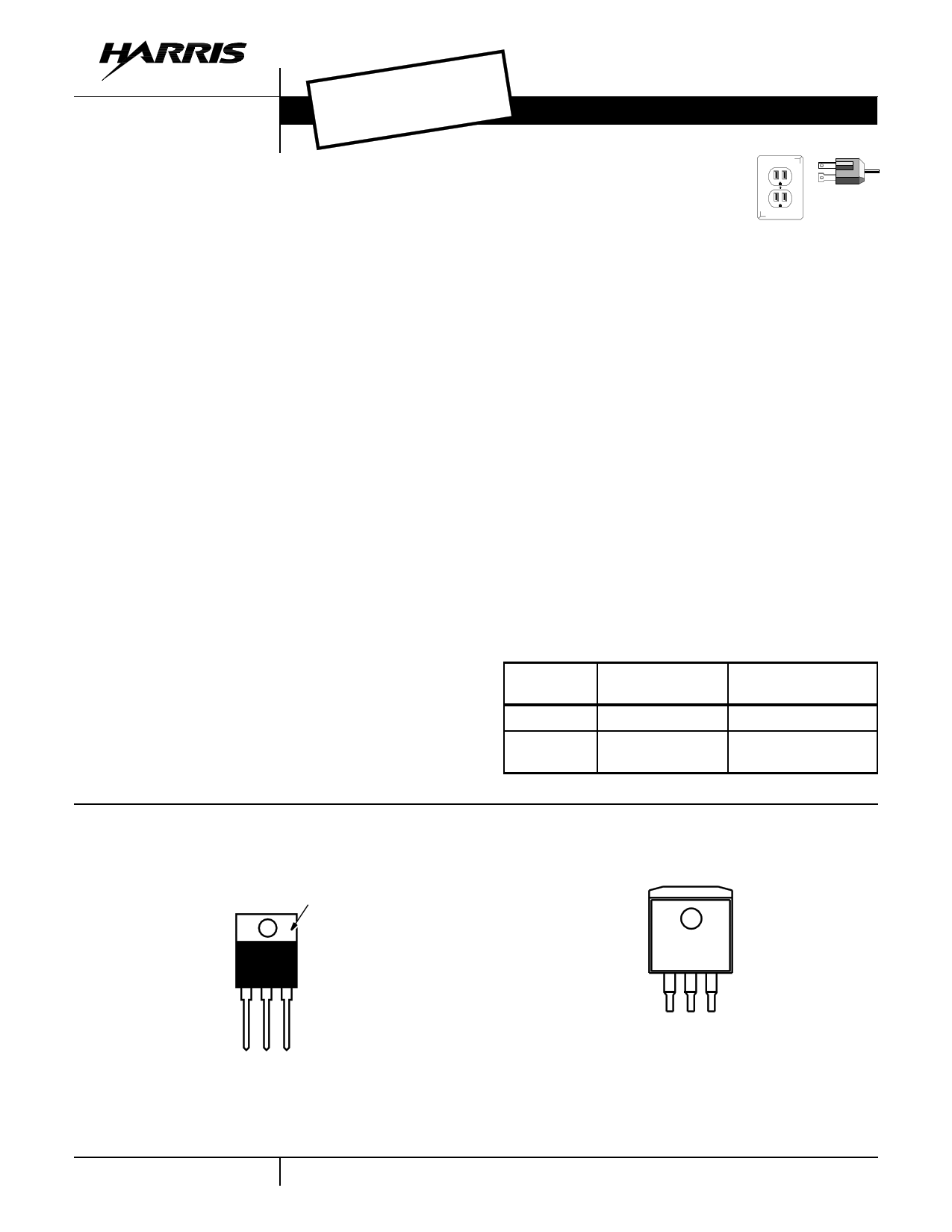
Pinouts
HIP5600 (TO-220)
TOP VIEW
TAB ELECTRICALLY
CONNECTED
TO VOUT
VOUT
Features
• Operates from 50VDC to 400VDC
• Operates from 50VRMS to 280VRMS Line
• UL Recognized
• Variable DC Output Voltage 1.2VDC to VIN - 50V
• Internal Thermal Shutdown Protection
• Internal Over Current Protection
• Up to 40mA Peak Output Current
• Surge Rated to ±650V; Meets IEEE/ANSI C62.41.1980
with Additional MOV
CAUTION: This product does not provide isolation from AC
line.
Applications
• Switch Mode Power Supply Start-Up
• Electronically Commutated Motor Housekeeping Supply
• Power Supply for Simple Industrial/Commercial/Consumer
Equipment Controls
• Off-Line (Buck) Switch Mode Power Supply
Ordering Information
PART
NUMBER
HIP5600IS
HIP5600IS2
TEMP. RANGE
-40oC to +100oC
-40oC to +100oC
PACKAGE
3 Lead Plastic SIP
3 Lead Gullwing Plastic
SIP
HIP5600 (MO-169)
TOP VIEW
HIP5600
1 CAUTION: These devices are sensitive to electrostatic discharge; follow proper IC Handling Procedures.
Copyright © Harris Corporation 1998
1 page 
HIP5600
VOUT = VREF + VZ
(EQ. 3)
Error Budget
∆V O U T
=
∆VTR
E
F
+
∆V
T
Z
(EQ. 4A)
∆V
T
R
E
F
≡
∆V R E F
+
VREFL
OADR
E
G
(
∆IO
U
T
)
+
VR
E
F
T
C
(
∆T e m
p
)
+
VREFT
C
(
θS
A
)
∆( I O
U
T
⋅
VIN
)
+
V
REFLINER
E
G
(EQ. 4B)
∆V
T
Z
≡
VZ
t
o
l
e
r
a
n
c
e(VZ
)
+
VZT
C
(
∆T
e
m
p)
(EQ. 4C)
of HIP5600 and the zener diode (∆VREF and ∆Vz), load reg-
ulation of the HIP5600 (VREF LOAD REG), and the effects of
temperature on the HIP5600 and the zener diode (VREFTC,
VZTC).
Example: Given: VIN = 200V, VOUT = 14.18V (VREF =
1.18V, VZ = 13V), ∆VZ = 5%, VZTC = +0.079%
1N5243BPH), ∆IOUT equal 10mA and ∆Temp
/°C (assumes
equal +60oC.
The worst case ∆VOUT is 0.4956V. The shift in VOUT is
attributed to the following: -0.2 (HIP5600) and 0.69 (zener
diode).
The regulator/zener diode configuration gives a 3.5%
(0.49/14.18) worst case output voltage error where, for the
same conditions, the regulator/resistor configuration results
in an 7.5% (1.129/15) worst case output voltage error.
External Capacitors
A minimum10µF output capacitor (C2) is required for stability
of the output stage. Any increase of the load capacitance
greater than 10µF will merely improve the loop stability and
output impedance.
A 0.02µF input decoupling capacitor (C1) between VIN and
ground may be required if the power source impedance is
not sufficiently low for the 1MHz - 10MHz band. Without this
capacitor, the HIP5600 can oscillate at 2.5MHz when driven
by a power source with a high impedance for the 1MHz -
10MHz band.
An optional bypass capacitor (C3) from VADJ to ground
improves the ripple rejection by preventing the ripple at the
Adjust pin from being amplified. Bypass capacitors larger
than 10µF do not appreciably improve the ripple rejection of
the part (see Figure 20 through Figure 25).
Load Regulation
For improved load regulation, resistor RF1 (connected
between the adjustment terminal and VOUT) should be tied
directly to the output of the regulator (Figure 4A) rather than
near the load Figure 4B. This eliminates line drops (RS) from
appearing effectively in series with RF1 and degrading regu-
lation. For example, a 15V regulator with a 0.05Ω resistance
between the regulator and the load will have a load regula-
tion due to line resistance of 0.05Ω x ∆IL. If RF1 is con-
nected near the load the effective load regulation will be 11.9
times worse (1+R2/R1, where R2 = 12k, R1 = 1.1k).
HIP5600
AC/DC
HIP5600
AC/DC
RS
VREF
IADJ
I1
RF1 VOUT
RF2
RS
VREF I1
RF1
IADJ
RF2
VOUT
AC/DC
AC/DC
(A) (B)
FIGURE 4.
Protection Diodes
The HIP5600, unlike other voltage regulators, is internally
protected by input diodes in the event the input becomes
shorted to ground. Therefore, no external protection diode is
required between the input pin and the output pin to protect
against the output capacitor (C2) discharging through the
input to ground.
If the output is shorted in the absence of D1 (Figure 5), the
bypass capacitor voltage (C3) could exceed the absolute
maximum voltage rating of ±5V between VOUT and VIN.
Note; No protection diode (D1) is needed for output voltages
less than 6V or if C3 is not used.
HIP5600
C3
10µF
RF1 D1
RF2
VIN
C1
0.02µF
D1 PROTECTS AGAINST C3
DISCHARGING WHEN THE
OUTPUT IS SHORTED.
+ VOUT
C2
10µF
FIGURE 5. REGULATOR WITH PROTECTION DIODE
Selecting the Right Heat Sink
Linear power supplies can dissipate a lot of power. This
power or heat must be safely dissipated to permit continuous
operation. This section will discuss thermal resistance and
show how to calculate heat sink requirements.
Electronic heat sinks are generally rated by their thermal
resistance. Thermal resistance is defined as the temperature
rise per unit of heat transfer or power dissipated, and is
expressed in units of degrees centigrade per watt. For a par-
ticular application determine the thermal resistance (θSA)
which the heat sink must have in order to maintain a junction
temperature below the thermal shut down limit (TTS).
5
5 Page 
HIP5600
HIP5600
START-UP PROTECTION
P-IGBT
SNUBBER CIRCUIT
RF1
C3 RF2
RF3
+
DC
FAN
-
FIGURE 17. HIGH CURRENT “BUCK” REGULATOR CONCEPT
Typical Performance Curves
-0.4
1mA TO 10mA
-0.6
-0.8
-1.0 1mA TO 20mA
-1.2
-1.4
1mA TO 30mA
VIN = 50VDC
-1.6 -40
-20
0 25 40 60 80 100
CASE TEMPERATURE (oC)
FIGURE 18. LOAD REGULATION vs TEMPERATURE
-1
-2
-3 1mA TO 10mA
-4
-5
-6 1mA TO 20mA
-7
-8 1mA TO 30mA
-9
VIN = 400VDC
-10
-40
-20 0 25 40 60
CASE TEMPERATURE (oC)
80
FIGURE 19. LOAD REGULATION VS. TEMPERATURE
85
80 VIN = 170VDC, IL = 10mA, f = 120Hz, TC = +25oC
75
70 1µF BYPASS CAPACITOR
65 10µF BYPASS CAPACITOR
60
55
50 NO BYPASS CAPACITOR
45
0 10 20 30 40 50 60 70 80 90 100 110
OUTPUT VOLTAGE (V)
90
VIN = 400VDC, IL = 10mA, f = 120Hz, TC = +25oC
80
70
1µF BYPASS CAPACITOR
10µF BYPASS CAPACITOR
60
50
40 NO BYPASS CAPACITOR
30 0 50 100 150 200 250 300 350
OUTPUT VOLTAGE (V)
FIGURE 20. RIPPLE REJECTION RATIO (OUTPUT VOLTAGE) FIGURE 21. RIPPLE REJECTION RATIO (OUTPUT VOLTAGE)
11
11 Page | ||
| Páginas | Total 16 Páginas | |
| PDF Descargar | [ Datasheet HIP5600.PDF ] | |
Hoja de datos destacado
| Número de pieza | Descripción | Fabricantes |
| HIP5600 | Thermally Protected High Voltage Linear Regulator | Harris Corporation |
| HIP5600IS | Thermally Protected High Voltage Linear Regulator | Harris Corporation |
| HIP5600IS2 | Thermally Protected High Voltage Linear Regulator | Harris Corporation |
| Número de pieza | Descripción | Fabricantes |
| SLA6805M | High Voltage 3 phase Motor Driver IC. |
Sanken |
| SDC1742 | 12- and 14-Bit Hybrid Synchro / Resolver-to-Digital Converters. |
Analog Devices |
|
DataSheet.es es una pagina web que funciona como un repositorio de manuales o hoja de datos de muchos de los productos más populares, |
| DataSheet.es | 2020 | Privacy Policy | Contacto | Buscar |