|
|
|
PDF IR3843AMPBF Data sheet ( Hoja de datos )
| Número de pieza | IR3843AMPBF | |
| Descripción | HIGHLY EFFICIENT INTEGRATED 3A SYNCHRONOUS BUCK REGULATOR | |
| Fabricantes | International Rectifier | |
| Logotipo | ||
Hay una vista previa y un enlace de descarga de IR3843AMPBF (archivo pdf) en la parte inferior de esta página. Total 30 Páginas | ||
|
No Preview Available !
PD-97509
IR3843AMPbF
SupIRBuckTM
HIGHLY EFFICIENT
INTEGRATED 3A SYNCHRONOUS BUCK REGULATOR
Features
• Wide Input Voltage Range 1.5V to 21V
• Wide Output Voltage Range 0.7V to 0.9*Vin
• Continuous 3A Load Capability
• Integrated Bootstrap-diode
• High Bandwidth E/A for excellent transient
performance
• Programmable Switching Frequency up to 1.2MHz
• Programmable Over Current Protection
• PGood output
• Hiccup Current Limit
• Precision Reference Voltage (0.7V, +/-1%)
• Programmable Soft-Start
• Enable Input with Voltage Monitoring Capability
• Enhanced Pre-Bias Start-up
• Seq input for Tracking applications
• -40oC to 125oC operating junction temperature
• Thermal Protection
• Multiple current ratings in pin compatible footprint
• 5mm x 6mm Power QFN Package, 0.9 mm height
• Lead-free, halogen-free and RoHS compliant
Description
The IR3843A SupIRBuckTM is an easy-to-use,
fully integrated and highly efficient DC/DC
synchronous Buck regulator. The MOSFETs co-
packaged with the on-chip PWM controller make
IR3843A a space-efficient solution, providing
accurate power delivery for low output voltage
applications.
IR3843A is a versatile regulator which offers
programmability of start up time, switching
frequency and current limit while operating in
wide input and output voltage range.
The switching frequency is programmable from
250kHz to 1.2MHz for an optimum solution.
It also features important protection functions,
such as Pre-Bias startup, hiccup current limit and
thermal shutdown to give required system level
security in the event of fault conditions.
Applications
• Server Applications
• Storage Applications
• Embedded Telecom Systems
• Distributed Point of Load Power Architectures
• Netcom Applications
• Computing Peripheral Voltage Regulators
• General DC-DC Converters
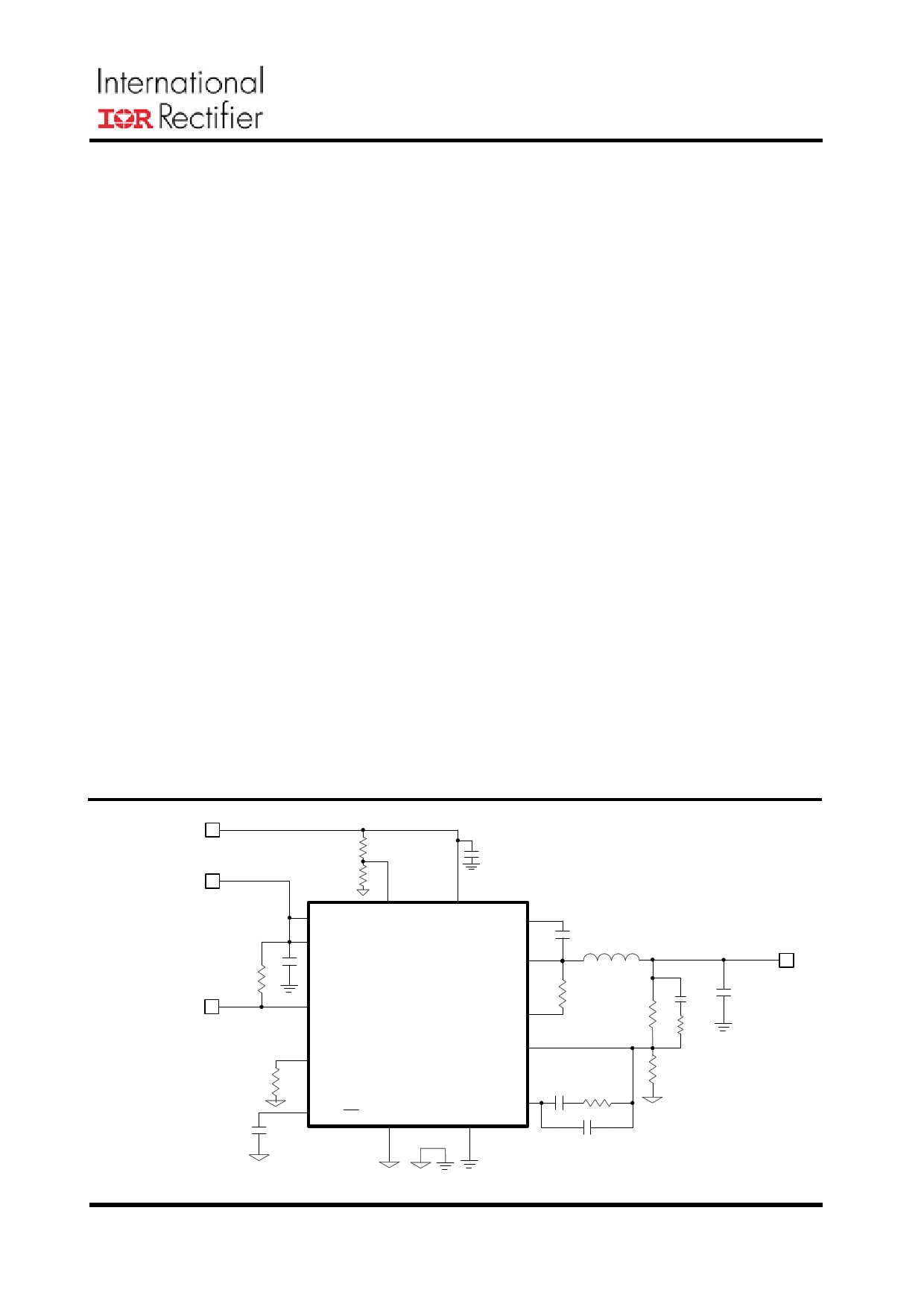
1.5V <Vin<16V
4.5V <Vcc<5.5V
PGood
Seq Enable
Vcc
PGood
Rt
SS/ SD Gnd
Vin Boot
SW
OCSet
Fb
Comp
PGnd
Vo
Rev 16.0
Fig. 1. Typical application diagram
1
Free Datasheet http://www.datasheet4u.com/
1 page 
Recommended Operating Conditions
PD-97509
IR3843AMPbF
Symbol
Vin
Vcc
Boot to SW
Vo
Io
Fs
Tj
Definition
Input Voltage
Supply Voltage
Supply Voltage
Output Voltage
Output Current
Switching Frequency
Junction Temperature
Min
Max
Units
1.5 21*
4.5 5.5
4.5 5.5 V
0.7 0.9*Vin
0 3A
225
1320
kHz
-40 125 oC
* SW must not exceed the Abs Max Rating (25V)
Electrical Specifications
Unless otherwise specified, these specification apply over 4.5V< Vcc<5.5V, Vin=12V, 0oC<Tj< 125oC.
Typical values are specified at Ta = 25oC.
Parameter
Symbol
Test Condition
Min
TYP MAX
Units
Power Loss
Power Loss
MOSFET Rds(on)
Top Switch
Bottom Switch
Reference Voltage
Feedback Voltage
Acc urac y
Ploss
Rds(on)_Top
Rds(on)_Bot
VFB
Vcc=5V, Vin=12V, Vo=1.8V, Io=3A,
Fs=600kHz, L=2.2uH, Note4
VBoo t -Vsw =5V, ID=3A, Tj=25oC
Vcc=5V, ID=3A, Tj=25oC
0oC<Tj<125oC
-40oC<Tj<125oC, Note3
0.682
W
24.5
24.5
32
32
mΩ
0.7
-1.0 +1.0
-2.0 +2.0
V
%
Supply Current
VCC Supply Current (Standby)
Vcc Supply Current (Dyn)
I CC( Sta nd by)
ICC(Dyn)
Under Voltage Lockout
VCC-S tart- Threshold
V CC_UVLO_S tart
VCC-S top-T hreshold
Enable-St ar t-T hreshold
V CC_UVLO_S top
E nable_UVLO_St ar t
Enable-Stop-Threshold
E nable_UVLO_St op
Enable leakage current
Ien
SS=0V, No Switching, Enable low
SS=3V, Vcc=5V, Fs=500kHz
Enable high
Vcc Rising Trip Level
Vcc Falling Trip Level
Supply ramping up
Supply ramping down
Enable=3.3V
500
10
μA
mA
3.95
3.65
1.14
0.9
4.15
3.85
1.2
1.0
4.35
4.05
1.36
1.06
15
V
μA
Rev 16.0
5
Free Datasheet http://www.datasheet4u.com/
5 Page 
PD-97509
IR3843AMPbF
Typical Efficiency and Power Loss Curves
Vin=5V, Vcc=5V, Io=0.3A-3A, Fs=600kHz, Room Temperature, No Air Flow
The table below shows the inductors used for each of the output voltages
in the efficiency measurement.
Vout (V) L (uH)
P/N
0.7
0.75
0.9
1
1.1
1.2
1.5
1.8
2.5
3.3
0.82
0.82
1
1.5
1.5
1.5
1.5
1.5
1.5
1.5
IHLP2525EZ-01 2.2uH
IHLP2525EZ-01 2.2uH
PCMB065T-1R0MS
PCMB065T-1R5MS
PCMB065T-1R5MS
PCMB065T-1R5MS
PCMB065T-1R5MS
PCMB065T-1R5MS
PCMB065T-1R5MS
PCMB065T-1R5MS
DCR
(mΩ)
4.6
4.6
5.6
6.7
6.7
6.7
6.7
6.7
6.7
6.7
Rev 16.0
98
96
94
92
90
88
86
84
82
80
78
76
74
72
70
0.3
0.7V
0.6
0.75V
0.9
0.9V
1.2 1.5 1.8 2.1 2.4 2.7
Iout (A)
3
1V 1.1V 1.2V 1.5V 1.8V 2.5V 3.3V
0.55
0.5
0.45
0.4
0.35
0.3
0.25
0.2
0.15
0.1
0.05
0.3
0.7V
0.6
0.75V
0.9
0.9V
1.2 1.5 1.8 2.1 2.4 2.7
Iout (A)
3
1V 1.1V 1.2V 1.5V 1.8V 2.5V 3.3V
11
Free Datasheet http://www.datasheet4u.com/
11 Page | ||
| Páginas | Total 30 Páginas | |
| PDF Descargar | [ Datasheet IR3843AMPBF.PDF ] | |
Hoja de datos destacado
| Número de pieza | Descripción | Fabricantes |
| IR3843AMPBF | HIGHLY EFFICIENT INTEGRATED 3A SYNCHRONOUS BUCK REGULATOR | International Rectifier |
| Número de pieza | Descripción | Fabricantes |
| SLA6805M | High Voltage 3 phase Motor Driver IC. |
Sanken |
| SDC1742 | 12- and 14-Bit Hybrid Synchro / Resolver-to-Digital Converters. |
Analog Devices |
|
DataSheet.es es una pagina web que funciona como un repositorio de manuales o hoja de datos de muchos de los productos más populares, |
| DataSheet.es | 2020 | Privacy Policy | Contacto | Buscar |