|
|
|
PDF IR1155S Data sheet ( Hoja de datos )
| Número de pieza | IR1155S | |
| Descripción | uPFC ONE CYCLE CONTROL PFC IC | |
| Fabricantes | International Rectifier | |
| Logotipo | ||
Hay una vista previa y un enlace de descarga de IR1155S (archivo pdf) en la parte inferior de esta página. Total 21 Páginas | ||
|
No Preview Available !
Feb 28, 2011
IR1155S
PROGRAMMABLE FREQUENCY, ONE CYCLE CONTROL PFC IC
Features
• PFC IC with IR proprietary “One Cycle Control”
• Continuous conduction mode boost type PFC
• Programmable switching frequency (48k-200kHz)
• Average current mode control
• Output overvoltage protection
• Open loop protection
• Cycle by cycle peak current limit
• VCC under voltage lockout
• Programmable soft start
• Micropower startup
• User initiated micropower “Sleep Mode”
• OVP/EN pin internal filtering for higher noise immunity
• 1.5A peak gate drive
• Latch immunity and ESD protection
Description
The μPFC IR1155 power factor correction IC, based on IR proprietary "One
Cycle Control" (OCC) technique, provides for high PF, low THD and
excellent DC Bus regulation while enabling drastic reduction in component
count, PCB area and design time as compared to traditional solutions. The
IC is designed to operate in continuous conduction mode Boost PFC
converters with average current mode control over 85-264VAC input line
voltage range. Switching frequency can be programmed to anywhere
between 48kHz to 200kHz based on the specific application requirement.
In addition, IR1155 offers several advanced system-enabling and protective
features such as dedicated pin for over voltage protection, cycle by cycle
peak current limitation, open loop protection, VCC UVLO, soft-start and
micropower startup/sleep-mode with IC current consumption less than
200µA. The sleep mode, invoked by pulling the OVP/EN pinhttp://www.DataSheet4U.com/ low, enables
compliance with standby power requirements mandated by regulations
such as Energy Star, Green Power, Blue Angel etc.
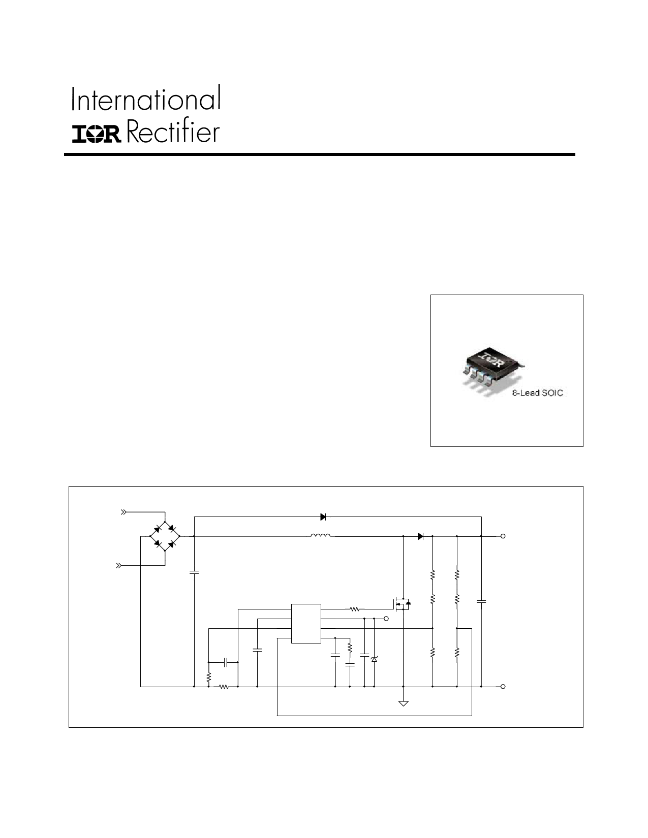
Package
IR1155 Application Diagram
AC LINE
-
+
AC NEUTRAL
VOUT
1 COM GATE 8
2 FREQ VCC 7
3 ISNS VFB 6
4 OVP COMP 5
IR1155S
VCC
RTN
www.irf.com
© 2011 International Rectifier
1 page 
IR1155S
Internal Voltage Reference Section
Parameter
Reference Voltage
Line Regulation
Temp Stability
Total Variation
Symbol
VREF
RREG
TSTAB
ΔVTOT
Voltage Error Amplifier Section
Parameter
Symbol
Transconductance
Source Current
gm
IOVEA(SRC)
Sink Current
IOVEA(SNK)
Soft Start Delay Time
tSS
Min.
4.9
4.85
Min.
35
30
20
-57
-90
VCOMP Voltage (Fault)
Effective VCOMP Voltage
VFB Input Bias Current
Output Low Voltage
Output High Voltage
VCOMP Start Voltage
VCOMP FLT
VCOMP EFF
IIB(Bias)
VOL
VOH
VCOMP START
4.6
5
240
Typ.
5
10
0.4
Max.
5.1
20
5.1
Units Remarks
V TA = 25°C
mV 14 V < VCC < 19V
% -25°C ≤ TAMB ≤ 125°C
V Line & Temperature
Typ.
50
44
44
-43
-43
35
Max.
65
58
90
-30
-20
1 1.4
4.9
http://www.DataSheet4U.com/
340
5.2
-0.2
0.25
5.4
460
Units Remarks
µS
µA
µA
msec
V
TAMB = 25°C
-25°C ≤TAMB≤ 125°C
TAMB = 25°C
-25°C ≤TAMB≤ 125°C
RGAIN = 1kΩ, CZERO = 0.33uF,
CPOLE = 0.01uF
@ 100µA steady state
current
V
µA VFB=4.9V
V
V
mV
www.irf.com
5 © 2011 International Rectifier
5 Page 
IR1155S
IR1155 General Description
The μPFC IR1155 IC is intended for power factor
correction in continuous conduction mode Boost
PFC converters operating at fixed switching
frequency with average current mode control.
The switching frequency is programmable any
where from 48kHz to 200khz. The IC operates
according to IR's proprietary "One Cycle Control"
(OCC) PFC algorithm, which is based on the re-
settable integrator principle. When operating a
AC-DC Boost converter, power factor correction
can be achieved using this algorithm without AC
input line sensing.
Theory of Operation
The OCC algorithm works using two loops - a
slow outer voltage loop and a fast inner current
loop. The outer voltage loop monitors the VFB
pin to maintain regulation of boost converter
output voltage and generates a constant error
signal. The inner current loop exploits the
embedded input voltage information in the boost
converter duty cycle to generate a current
reference for power factor correction. The
combination of the two control elements forces
the amplitude and shape of the input current to
be proportional to and in phase with the input
voltage while maintaining output voltage
regulation. This is true so long as operation in
continuous conduction mode is maintained.
Average current mode operation is envisaged by
filtering the switching frequency ripple from the
current sense signal in the current loop using an
on-chip filter.
The IC determines the boost converter
instantaneous duty cycle using the voltage
feedback loop error signal Vm and the current
sense signal VISNS, which is the voltage at the
current sense pin of the IC. The PWM ramp is
generated using a resettable integrator that
tracks Vm every switching cycle. The current
sense signal is amplified by the current amplifier
averaged to remove the ripple component and
fed into the summing node where it is subtracted
from the voltage error signal, Vm. The resulting
voltage (Vm - gDC.VISNS) is compared with the
PWM ramp signal by the PWM comparator to
determine the gate drive duty cycle. The
instantaneous duty cycle is mathematically given
by:
D = (Vm - gDC.VISNS) /Vm
A more detailed description of IR1155 theory of
operation is available in Application Note.
Feature set
The IR1155 offers a host of advanced features and
system protections functions, which makes it the
most feature-intensive IC in PFC market in a
compact 8-pin package.
User-Programmable Switching Frequency
IR1155 IC operates under fixed switching
frequency. The switching frequency is user-
programmed by inserting a capacitor between
FREQ & COM pins. A pair of current sources inside
the IC source/sink current in/out of the capacitor
alternately thus generating a constant-slope saw-
tooth ramp signal between a pre-determined peak &
valley voltage pair (typically between 2V to 4V). This
saw-tooth signal is the oscillator signal of the IC.
The frequency of operation of the IC can be
programmed anywhere between 48kHz and 200kHz
by suitably sizing the capacitor. The oscillator signal
is a key control signal and is used by the resettable
integrator block of the IC to generate the internal
PWM ramp every switching cycle.
IC Supply Circuit & Low start-up current
The IR1155 UVLO circuit maintains the IC in UVLO
mode during start-up if VCC pin voltage is less than
the VCC turn-on threshold, VCC,ON and current
http://www.DataSheet4U.com/
consumption is less than ICC,START. Should VCC pin
voltage should drop below UVLO threshold VCC, UVLO
anytime after start-up, the IC is pushed back into
UVLO mode (VCOMP pin is discharged) and VCC
pin has to exceed VCC,ON again to re-start operation.
It is noted that there is no internal clamping of the
VCC pin.
User initiated Micropower Sleep mode
The IC can be actively pushed into a micropower
sleep mode where current consumption is less than
ICC,SLEEP by pulling OVP/EN pin below the Sleep
threshold, VSLEEP(OFF), even while VCC is above
VCC,ON. This allows the user to disable PFC during
application stand-by situations in order to meet
regulations (Blue Angel, Green Power etc). When
OVP/EN pin is pulled low, the VCOMP pin of the IC
is actively discharged as the IC is relegated to the
Sleep mode. This enables the IC to go through soft-
start when the IC is re-enabled. Since VSLEEP(OFF) is
less than 1V, even logic level signals can be
employed to disable and enable the IC.
www.irf.com
11 © 2011 International Rectifier
11 Page | ||
| Páginas | Total 21 Páginas | |
| PDF Descargar | [ Datasheet IR1155S.PDF ] | |
Hoja de datos destacado
| Número de pieza | Descripción | Fabricantes |
| IR1155S | uPFC ONE CYCLE CONTROL PFC IC | International Rectifier |
| Número de pieza | Descripción | Fabricantes |
| SLA6805M | High Voltage 3 phase Motor Driver IC. |
Sanken |
| SDC1742 | 12- and 14-Bit Hybrid Synchro / Resolver-to-Digital Converters. |
Analog Devices |
|
DataSheet.es es una pagina web que funciona como un repositorio de manuales o hoja de datos de muchos de los productos más populares, |
| DataSheet.es | 2020 | Privacy Policy | Contacto | Buscar |