|
|
|
PDF ISL6186 Data sheet ( Hoja de datos )
| Número de pieza | ISL6186 | |
| Descripción | USB Port Power Supply Controller | |
| Fabricantes | Intersil Corporation | |
| Logotipo | ||
Hay una vista previa y un enlace de descarga de ISL6186 (archivo pdf) en la parte inferior de esta página. Total 18 Páginas | ||
|
No Preview Available !
www.DataSheet.co.kr
USB Port Power Supply Controller
ISL6186
The ISL6186 USB power controller family provides
overcurrent (OC) fault protection for one or more USB ports.
This product family consists of eight individual functional
product variants and three package options and is operation
rated for a nominal +2.5V to +5V range and specified over
the full commercial and industrial temperature ranges.
Each ISL6186 type incorporates a 45mΩ P-channel MOSFET
power switch for power control and features internal current
monitoring, accurate current limiting, and current limited
delay to turn-off for system supply protection along with
control and communication I/O.
The ISL6186 family offers product variants with specified
continuous output current levels of 1.5A, 3A or 3.6A, enable
active high or low inputs, and latch off or automatic retry after
overcurrent turn-off, making these devices well suited for many
low-power applications.
This family of ICs is offered in an industry standard SOIC package
as well as in the 70% smaller 3x3 DFN package, which provides
the same performance and an additional Power-Good output
feature in the smallest possible (10 Ld DFN) package.
Features
• 2.5V to 5V Operating Range
• 45mΩ Integrated Power P-channel MOSFET Switches
• Continuous Current Options for 1.5A, 3A and 3.6A
• Thermally Insensitive 12ms of Current Limiting Prior to
Turn-Off
• Output Discharges with Reverse Current Blocking When
Disabled
• Latch-off or Auto Restart and Enable Polarity Options
• 1µA Off-State Supply Current
• Industry Standard Pin-for-Pin SOIC and Smaller DFN
Packages Available
Applications
• USB Port Power Management Including USB 3.0
• Low Power Electronic Circuit Limiting and Breaker
U
S
B
C
O
N +5V
T
R
O
L
L
E
R
D+
D-
ENABLE
OUT
FAULT
VIN GND
ISL6186
D+
D-
USB PORT POWER
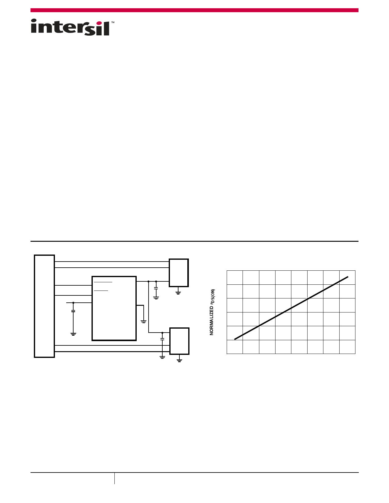
FIGURE 1. TYPICAL APPLICATION
USB
PORT 1
VBUS
VBUS
USB
PORT_2
1.3
1.2
1.1
1.0
0.9
0.8
0.7
-40
-25
0 25 45 75
TEMPERATURE (°C)
85
FIGURE 2. NORMALIZED rDS(ON) TEMPERATURE
CHARACTERISTIC CURVE
115
September 1, 2011
FN7698.1
1
CAUTION: These devices are sensitive to electrostatic discharge; follow proper IC Handling Procedures.
1-888-INTERSIL or 1-888-468-3774 |Copyright Intersil Americas Inc. 2011. All Rights Reserved
Intersil (and design) is a trademark owned by Intersil Corporation or one of its subsidiaries.
All other trademarks mentioned are the property of their respective owners.
Datasheet pdf - http://www.DataSheet4U.net/
1 page 
www.DataSheet.co.kr
ISL6186
Absolute Maximum Ratings
Supply Voltage (VIN to GND, Note 7) . . . . . . . . . . . . . . . . . . . . . . . . . . . .6.5V
EN, FAULT. . . . . . . . . . . . . . . . . . . . . . . . . . . . . . . . . . . . . . . . . . . . . . . . . . . .VIN
OUT . . . . . . . . . . . . . . . . . . . . . . . . . . . . . . . . . . . . . . . . GND - 0.3V to VIN 0.3V
Output Current . . . . . . . . . . . . . . . . . Short Circuit Protected; Limited to 5A
ESD Rating
Human Body Model (Per MIL-STD-883 Method 3015.7) . . . . . . . . . . 3kV
Machine Model (Per MIL-STD-883 Method 3015.7) . . . . . . . . . . . . 300V
Latch Up (Tested per JESD-78B; Class 2, Level A) . . . . . . . . . . . . . . 100mA
Thermal Information
Thermal Resistance (Typical)
θJA (°C/W) θJC (°C/W)
8 Lead SOIC Package (Note 4) . . . . . . . . . .
120
N/A
8 Lead 3x3 DFN Package (Notes 5, 6) . . .
48
6
10 Lead 3x3 DFN Package (Notes 5, 6) . .
48
6
Maximum Junction Temperature . . . . . . . . . . . . . . . . . . . . . . . . . . . +150°C
Maximum Storage Temperature Range . . . . . . . . . . . . . . -65°C to +150°C
Pb-Free Reflow Profile . . . . . . . . . . . . . . . . . . . . . . . . . . . . . . . .see link below
http://www.intersil.com/pbfree/Pb-FreeReflow.asp
Operating Conditions
Commercial Temperature Range . . . . . . . . . . . . . . . . . . . . . . 0°C to +70°C
Industrial Temperature Range . . . . . . . . . . . . . . . . . . . . . . . -40°C to +85°C
Supply Voltage Range (Typical). . . . . . . . . . . . . . . . . . . . . . . . . 2.5V to 5.5V
CAUTION: Do not operate at or near the maximum ratings listed for extended periods of time. Exposure to such conditions may adversely impact product
reliability and result in failures not covered by warranty.
NOTES:
4. θJA is measured with the component mounted on a high effective thermal conductivity test board in free air. See Tech Brief TB379 for details.
5. θJA is measured in free air with the component mounted on a high effective thermal conductivity test board with “direct attach” features. See Tech
Brief TB379.
6. For θJC, the “case temp” location is the center of the exposed metal pad on the package underside.
7. All voltages are relative to GND, unless otherwise specified.
Electrical Specifications VIN = 5V, TA = TJ, Unless Otherwise Specified. Boldface limits apply over the operating temperature
range, 0°C to +75°C or -40°C to +85°C.
SYMBOL
PARAMETER
TEST CONDITIONS
MIN MAX
(Note 8) TYP (Note 8)
UNITS
POWER SWITCH
rDS(ON)_50 ON-Resistance at 5.0V (Pulse Tested) VIN = 5V, IOUT = 0.5A, TA = TJ = +25°C
TA = TJ = +85°C
rDS(ON)_33 ON-Resistance at 3.3V (Pulse Tested) VIN = 3.3V, IOUT = 0.5A, TA = TJ = +25°C
TA = TJ = +85°C
rDS(ON)_25 On Resistance at 2.5V (Pulse Tested) VIN = 2.5V, IOUT = 0.5A, TA = TJ = +25°C
TA = TJ = +85°C
VOUT_DIS Disabled Output Voltage
VIN = 5V, Switch Disabled, 50µA Load
ROUT_PD Output Pull-Down Resistor
VIN = 5V, Switch Disabled
tR VOUT Rise Time
RL = 10Ω, CL = 10µF, 10% to 90%
tF Slow VOUT Turn-off Fall Time
RL = 10Ω, CL = 10µF, 90% to 10%
CURRENT CONTROL
- 45 48
- 50 54
- 54 57
- 61 64
- 65 69
- 74 79
- 22 45
3.4 5
6
- 10 -
- 200 -
mΩ
mΩ
mΩ
mΩ
mΩ
mΩ
mV
kΩ
µs
µs
IOUT_CONT_5
IOUT_CONT_5
IOUT_CONT_5
IOUT_CONT_3
IOUT_CONT_3
IOUT_CONT_3
IOUT_CONT_2
IOUT_CONT_2
IOUT_CONT_2
IOUT_CONT_2
Maximum Continuous Current,
VIN = 5V
Guaranteed by the Minimum Itrip
Current Specification
Maximum Continuous Current,
VIN = 3.3V
Guaranteed by the Minimum Itrip
Current Specification
Maximum Continuous Current,
VIN = 2.5V
ISL6186xA, B, E, F
ISL6186xC, D, G, H
ISL6186xI, J, K, L (10 Ld DFN)
ISL6186xA, B, E, F
ISL6186xC, D, G, H
ISL61861I, J, K, L (10 Ld DFN)
ISL6186xA, B, E, F
ISL61861C, D, G, H (SOIC)
ISL61862, ISL61863 C, D, G, H (DFN)
ISL61863I, J, K, L (10 Ld DFN)
- - 1.5
- - 3.0
- - 3.6
- - 1.5
- - 2.5
- - 2.7
- 1.2 -
- 1.8 -
-2-
-2-
A
A
A
A
A
A
A
A
A
A
5 FN7698.1
September 1, 2011
Datasheet pdf - http://www.DataSheet4U.net/
5 Page 
www.DataSheet.co.kr
ISL6186
Typical Performance Curves (Continued)
3A VARIANT
78A/ms
16A/ms
1.6A/ms
3A VARIANT
0.5A OC
300µs
1A OC
137µs
4A OC
32µs
2A OC
60µs
ILOAD = 2.75A
ILIMIT = 3.42A
ILOAD = 3.2A
ILIMITED
FIGURE 17. OC RAMP RATE ILIM WAVEFORMS
EN
FAULT
VOUT
3A VARIANT
IIN
FIGURE 19. TURN-ON INTO AN OVERCURRENT
EN
FAULT
VOUT
IIN
FIGURE 18. PEAK CURRENT SETTLING TIMES
EN
FAULT
VOUT
3A VARIANT
IIN
FIGURE 20. TURN-ON INTO MOMENTARY OC
VOUT
PG
EN
IIN
FIGURE 21. OVERCURRENT RETRY FUNCTION
11
FIGURE 22. TURN-OFF w PG
FN7698.1
September 1, 2011
Datasheet pdf - http://www.DataSheet4U.net/
11 Page | ||
| Páginas | Total 18 Páginas | |
| PDF Descargar | [ Datasheet ISL6186.PDF ] | |
Hoja de datos destacado
| Número de pieza | Descripción | Fabricantes |
| ISL6185 | Dual USB Port Power Supply Controller | Intersil Corporation |
| ISL6186 | USB Port Power Supply Controller | Intersil Corporation |
| Número de pieza | Descripción | Fabricantes |
| SLA6805M | High Voltage 3 phase Motor Driver IC. |
Sanken |
| SDC1742 | 12- and 14-Bit Hybrid Synchro / Resolver-to-Digital Converters. |
Analog Devices |
|
DataSheet.es es una pagina web que funciona como un repositorio de manuales o hoja de datos de muchos de los productos más populares, |
| DataSheet.es | 2020 | Privacy Policy | Contacto | Buscar |