|
|
|
PDF IRS2530S Data sheet ( Hoja de datos )
| Número de pieza | IRS2530S | |
| Descripción | DIM8TM DIMMING BALLAST CONTROL IC | |
| Fabricantes | International Rectifier | |
| Logotipo | ||
Hay una vista previa y un enlace de descarga de IRS2530S (archivo pdf) en la parte inferior de esta página. Total 23 Páginas | ||
|
No Preview Available !
www.DataSheet4U.net
July 09, 2008
IRS2530D(S)
DIM8TM DIMMING BALLAST CONTROL IC
IC Features
• Dimming ballast control plus half-bridge driver
• Closed-loop lamp current dimming control
• Internal non-ZVS protection
• Internal crest factor protection
• Programmable preheat time
• Fixed dead-time (2.0μs typ.)
• Lamp insert auto-restart
• Internal bootstrap MOSFET
• Internal 15.6V zener clamp diode on Vcc
• Micropower startup (250μA)
• Latch immunity and ESD protection
Product Summary
Topology
VOFFSET
VOUT
IO+ & IO- (typical)
Deadtime (typical)
Package Types
Half-Bridge
600 V
VCC
180mA & 260mA
2.0μs
Ballast System Features
• Single chip dimming solution
• Simple lamp current dimming control method
• Single lamp current sensing resistor required
• No half-bridge current-sensing resistor required
• No external protection circuits required (fully
internal)
PDIP8
SO8
• Flash-free lamp start at all dimming levels
• Large reduction in component count
• Easy to use for fast design cycle time
• Increased manufacturability and reliability
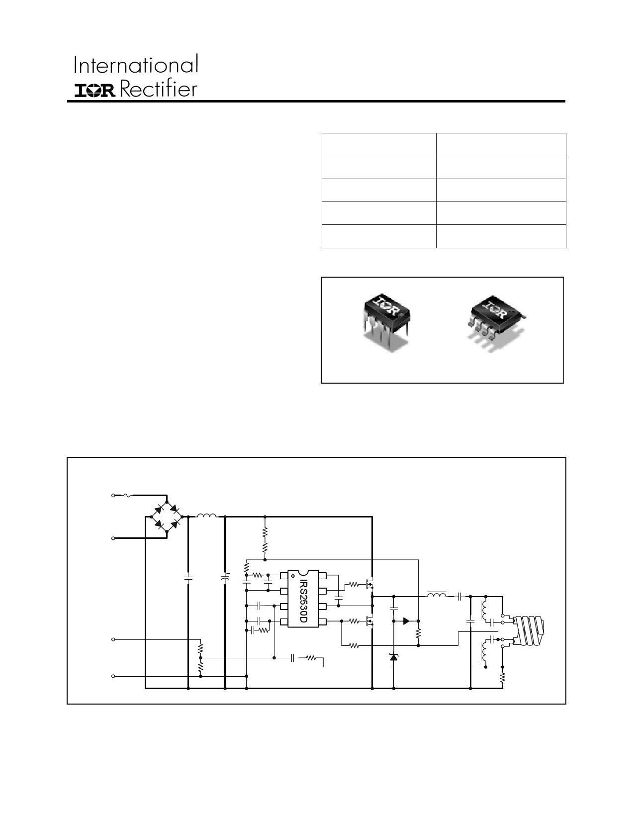
Typical Connection Diagram
Typical applications
• Linear dimming ballast (down to 10%)
• 3-way dimming ballast
• Multi-level switch dimming ballast
L
AC
LINE
INPUT
N
F1
(+)
1-10V
DIM
INPUT
(-)
BR1
LF
RVCC1
RVCC2
RLIM1
RLIM2 VCC
CF CBUS
1
CVCC1
CVCC2
CDIM
CVCO
COM
2
DIM
3
VCO
4
VB
8
HO
7
VS
6
LO
5
RHO
CBS
RLO
MHS
MLS
RDIM1
CPH RVCO
CFB
RFB
RLMP1
RDIM2
LRES:A
CDC
CSNUB
DCP2
RLMP2
CRES
DCP1
LRES:B
CH1
SPIRAL
CFL LAMP
CH2
LRES:C
RCS
www.irf.com
© 2008 International Rectifier
1
1 page 
www.DataSheet4U.net
IRS2530D(S)
Absolute Maximum Ratings
Absolute Maximum Ratings indicate sustained limits beyond which damage to the device may occur. All
voltage parameters are absolute voltages referenced to COM, all currents are defined positive into any lead.
The Thermal Resistance and Power Dissipation ratings are measured under board mounted and still air
conditions.
Symbol
VB
VS
VHO
VLO
VVCO
VDIM
ICC
IOMAX
dVS/dt
PD
PD
RθJA
RθJA
TJ
TS
TL
Definition
High-Side Floating Supply Voltage
High-Side Floating Supply Offset Voltage
High-Side Floating Output Voltage
Low-Side Output Voltage
VCO Input Voltage††
DIM Input Voltage
Supply Current†
Maximum allowable current at LO, HO and PFC due to
external power transistor Miller effect.
Allowable VS Pin Voltage Slew Rate
Maximum Power Dissipation @ TA ≤ +25ºC, 8-Pin DIP
Maximum Power Dissipation @ TA ≤ +25ºC, 8-Pin SOIC
Thermal Resistance, Junction to Ambient, 8-Pin DIP
Thermal Resistance, Junction to Ambient, 8-Pin SOIC
Junction Temperature
Storage Temperature
Lead Temperature (Soldering, 10 seconds)
Min.
-0.3
VB - 25
VS - 0.3
-0.3
-0.3
-0.3
---
-500
-50
---
---
---
---
-55
-55
---
Max.
625
VB + 0.3
VB + 0.3
VCC + 0.3
6
VCC + 0.3
20
500
50
1.0
0.625
85
128
150
150
300
Units
V
mA
V/ns
W
ºC/W
ºC
† This IC contains a zener clamp structure between the chip VCC and COM which has a nominal
breakdown voltage of 15.6V. This supply pin should not be driven by a DC, low impedance power
source greater than the VCLAMP specified in the Electrical Characteristics section.
†† This IC contains a zener clamp structure between the chip VCO and COM which has a nominal
breakdown voltage of 7.25V. This pin should not be driven by a DC, low impedance power source
greater than the VVCOMAX specified in the Electrical Characteristics section.
www.irf.com
© 2008 International Rectifier
5
5 Page 
www.DataSheet4U.net
State Diagram
Power Off
VCC < 10.5V (VCCUV-)
or
LO > 8.75V (VLOSD+)
(Lamp Removed)
VCC > 0V
UVLO Mode
Half-Bridge Off
IQCCUV ≅ 250μA
VCO = 0V
HO Off
LO Open Circuit
VCC > 12.5V (VCCUV+)
and
LO < 8.5V (VLOSD-)
(Lamp Inserted)
FAULT Mode
Fault Latch Set
Half-Bridge Off
IQCCUV ≅ 250μA
HO Off
LO Open Circuit
VCO > 4.0V
(VVCOFLT+)
(Lamp non-strike)
PH/IGN Mode
Half-Bridge Oscillating
Freq ramps from fMAX to fMIN
VCO Charging (1μA)
non-ZVS Disabled
Crest Factor Disabled
Lamp Ignites
CF > 5.5 (lamp removal)
ZVS
freq = freq + df
non-ZVS
ZVS OK
DIM Mode
Half-Bridge Oscillating @fDIM
Dimming Loop Enabled
non-ZVS Enabled
Crest Factor Enabled
IRS2530D(S)
VCC < 10.5V (VCCUV-)
www.irf.com
© 2008 International Rectifier
11
11 Page | ||
| Páginas | Total 23 Páginas | |
| PDF Descargar | [ Datasheet IRS2530S.PDF ] | |
Hoja de datos destacado
| Número de pieza | Descripción | Fabricantes |
| IRS2530D | DIM8TM DIMMING BALLAST CONTROL IC | International Rectifier |
| IRS2530S | DIM8TM DIMMING BALLAST CONTROL IC | International Rectifier |
| Número de pieza | Descripción | Fabricantes |
| SLA6805M | High Voltage 3 phase Motor Driver IC. |
Sanken |
| SDC1742 | 12- and 14-Bit Hybrid Synchro / Resolver-to-Digital Converters. |
Analog Devices |
|
DataSheet.es es una pagina web que funciona como un repositorio de manuales o hoja de datos de muchos de los productos más populares, |
| DataSheet.es | 2020 | Privacy Policy | Contacto | Buscar |