|
|
|
PDF DE275-102N06A Data sheet ( Hoja de datos )
| Número de pieza | DE275-102N06A | |
| Descripción | RF Power MOSFET | |
| Fabricantes | IXYS Corporation | |
| Logotipo | ||
Hay una vista previa y un enlace de descarga de DE275-102N06A (archivo pdf) en la parte inferior de esta página. Total 6 Páginas | ||
|
No Preview Available !
DE275-102N06A
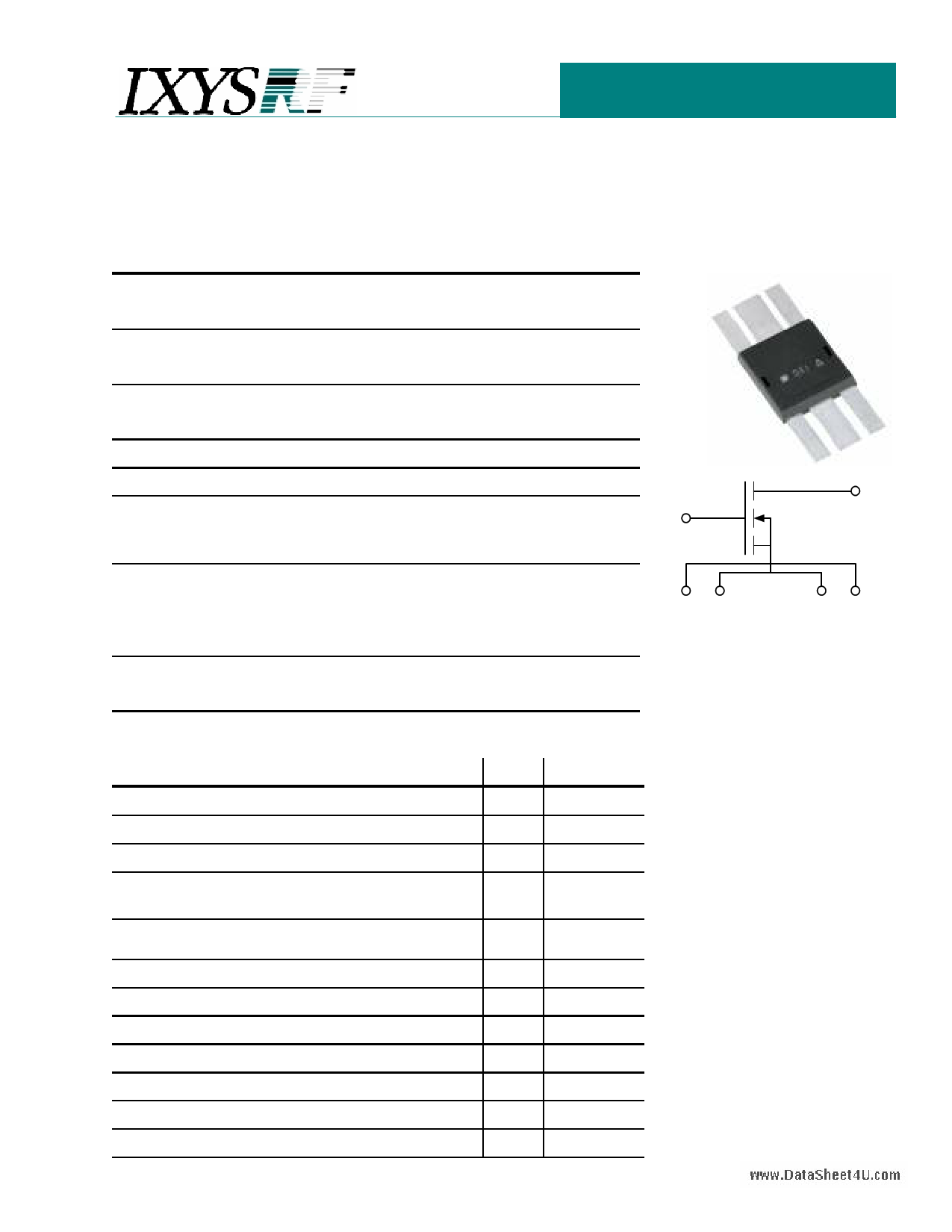
RF Power MOSFET
N-Channel Enhancement Mode
Low Qg and Rg
High dv/dt
Nanosecond Switching
Ideal for Class C, D, & E Applications
VDSS = 1000 V
ID25 =
8A
RDS(on) = 1.5 Ω
Symbol Test Conditions
Maximum Ratings
PDC = 590 W
VDSS
VDGR
VGS
VGSM
ID25
IDM
IAR
EAR
dv/dt
TJ = 25°C to 150°C
TJ = 25°C to 150°C; RGS = 1 MΩ
Continuous
Transient
Tc = 25°C
Tc = 25°C, pulse width limited by TJM
Tc = 25°C
Tc = 25°C
IS ≤ IDM, di/dt ≤ 100A/µs, VDD ≤ VDSS,
Tj ≤ 150°C, RG = 0.2Ω
IS = 0
1000
1000
±20
±30
8
48
6
20
5
V
V
V
V
A
A
A
mJ
V/ns
GATE
>200 V/ns
DRAIN
PDC
PDHS
PDAMB
RthJC
RthJHS
Symbol
Tc = 25°C
Derate 2.0W/°C above 25°C
Tc = 25°C
Test Conditions
590 W
300 W
3.0
0.25
0.50
W
C/W
C/W
Characteristic Values
TJ = 25°C unless otherwise specified
VDSS
VGS(th)
IGSS
IDSS
VGS = 0 V, ID = 3 mA
VDS = VGS, ID = 250 µA
VGS = ±20 VDC, VDS = 0
VDS = 0.8 VDSS TJ = 25°C
VGS = 0
TJ = 125°C
min.
1000
3.5
RDS(on)
VGS = 15 V, ID = 0.5ID25
Pulse test, t ≤ 300µS, duty cycle d ≤ 2%
gfs VDS = 20 V, ID = 0.5ID25, pulse test
www.DataSRhteheJHt4SU.com
TJ
TJM
Tstg
TL 1.6mm (0.063 in) from case for 10 s
Weight
2.5
-55
-55
typ. max.
V
5.0 V
±100 nA
50 µA
1 mA
1.5 Ω
4.3
0.50
175
300
2
7S
C/W
+175 °C
°C
+175 °C
°C
g
SG1 SG2
SD1 SD2
Features
• Isolated Substrate
− high isolation voltage (>2500V)
− excellent thermal transfer
− Increased temperature and power
cycling capability
• IXYS advanced low Qg process
• Low gate charge and capacitances
− easier to drive
− faster switching
• Low RDS(on)
• Very low insertion inductance (<2nH)
• No beryllium oxide (BeO) or other
hazardous materials
Advantages
• Optimized for RF and high speed
switching at frequencies to 100MHz
• Easy to mount—no insulators needed
• High power density
1 page 
Fig. 6 Class C Test Circuit
DE275-102N06A
RF Power MOSFET
250V
13.56MHz Class C RF Test Circuit
1. T1- 2:1 Turns ratio, Ferronics binocular core P/N 12-365-J
Primary - 2 turns of 26 AWG, single strand Teflon Wire.
Secondary - 1 turn of braid with the primary wire run inside of it.
2. L1 - < 90nH, 5 turns, 0.25" id, 18 AWG single strand mag-
net wire, 0.55" long.
3. C1 - 3000pf, 3 x 1000pf, ATC capacitors, P/N 102KW.
4. C2 - 470pf, ATC capacitor, P/N 471JW.
5. R1 - 3.3 ohm, 3 x 10 ohm Caddock resistors, P/N
MP850-10-10.
www.DataSheet4U.com
6. Q1 - DE275-102N06A
7. C3 - 5nf, 5 x .001uf, ceramic disc capacitors
8. C4 - 60pf - 100pf air variable capacitor
9. L2 - 800nH, 6 turns, 1" id, 12 AWG single strand magnet
wire, 0.85" long.
10. C5 - 250pf - 480pf mica compression capacitor, Sprague
Goodman GME90901.
11. L3 - 5.4uH, 20 turns, 18 AWG single strand magnet wire, Mi-
crometals core T-106-2, powered iron core.
12. C6A - 0.02uf, 2 x 0.01uf ceramic disc capacitors.
13. C6B - 0.08uf, 8 x 0.01uf ceramic disc capacitors.
14. FB1 - 3 x 900mu ferrite beads on 18 AWG buss wire.
5 Page | ||
| Páginas | Total 6 Páginas | |
| PDF Descargar | [ Datasheet DE275-102N06A.PDF ] | |
Hoja de datos destacado
| Número de pieza | Descripción | Fabricantes |
| DE275-102N06A | RF Power MOSFET | IXYS Corporation |
| Número de pieza | Descripción | Fabricantes |
| SLA6805M | High Voltage 3 phase Motor Driver IC. |
Sanken |
| SDC1742 | 12- and 14-Bit Hybrid Synchro / Resolver-to-Digital Converters. |
Analog Devices |
|
DataSheet.es es una pagina web que funciona como un repositorio de manuales o hoja de datos de muchos de los productos más populares, |
| DataSheet.es | 2020 | Privacy Policy | Contacto | Buscar |