|
|
|
PDF MT9V135 Data sheet ( Hoja de datos )
| Número de pieza | MT9V135 | |
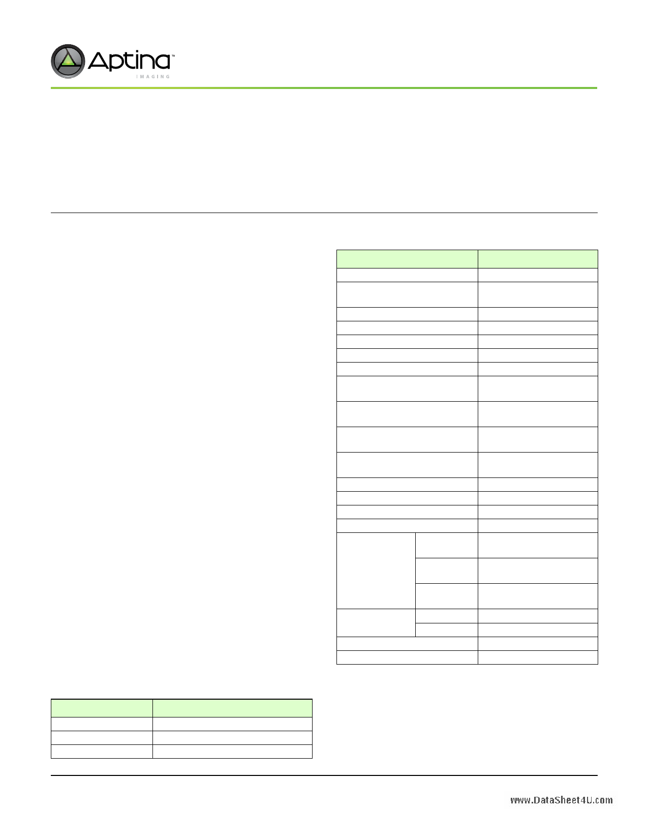
| Descripción | 1/4-Inch System-On-A-Chip (SOC) VGA NTSC and PAL CMOS Digital Image Sensor | |
| Fabricantes | Aptina Imaging Corporation | |
| Logotipo | ||
Hay una vista previa y un enlace de descarga de MT9V135 (archivo pdf) en la parte inferior de esta página. Total 30 Páginas | ||
|
No Preview Available !
MT9V135: 1/4-Inch System-On-A-Chip (SOC) VGA
Features
www.DataSheet4U.com
1/4-Inch System-On-A-Chip (SOC) VGA
NTSC and PAL CMOS Digital Image Sensor
MT9V135
For the latest data sheet, refer to Aptina’s Web site: www.aptina.com
Features
• DigitalClarity® CMOS imaging technology
• System-on-a-chip (SOC)—completely integrated
camera system
• NTSC and PAL (true two field) analog composite
video output
• Low power, interlaced scan CMOS image sensor
• ITU-R BT.656 parallel output (8-bit, interlaced)
• Serial LVDS data output
• Supports use of external devices for addition of
custom overlay graphics
• Superior low-light performance
• On-chip image flow processor (IFP) performs
sophisticated processing
• Color recovery and correction, sharpening, gamma,
lens shading correction, and on-the-fly defect
correction
• Automatic Features: Auto exposure (AE), auto white
balance (AWB), auto black reference (ABR), auto
flicker avoidance, auto color saturation, and auto
defect identification and correction
• Simple two-wire serial programming interface
Applications
• 900 MHz and 2.4 GHz wireless cameras
• Composite video and digital video out cameras
• CCTV security cameras
• Consumer video products
• Smart cameras
• Evidence quality cameras
• Cameras with the need for active or passive overlay
Data Sheet Applicable To
Silicon Revision: Rev4
Table 1:
Ordering Information
Part Number
MT9V135C12STC
MT9V135C12STCD ES
MT9V135C12STCH ES
Description
48-Pin CLCC ES (color)
48-pin CLCC ES Demo Kit (color)
48-pin CLCC ES Headboard (color)
Table 2:
Key Performance Parameters
Parameter
Typical Value
Optical format
Active imager size
Active pixels
NTSC output
PAL output
Pixel size
Color filter array
Shutter type
Maximum data rate/
master clock
Frame rate (VGA 640H x 480V)
Integration time
ADC resolution
Responsivity
Pixel dynamic range
SNRMAX
Supply voltage
I/O digital
Core digital
Analog
Power
Operating
consumption1
Standby
Operating temperature1
Package
1/4-inch (4:3)
3.63mm(H) x 2.78mm(V)
4.57mm diagonal
640H x 480V
720H x 486V
720H x 576V
5.6μm x 5.6μm
RGB paired Bayer pattern
Electronic rolling shutter
(ERS)
13.5 Mp/s
27 MHz
30 fps at 27 MHz (NTSC)
25 fps at 27 MHz (PAL)
16μs–33ms (NTSC)
16μs–40ms (PAL)
10-bit, on-chip
5 V/lux-sec (550nm)
70dB
39dB
2.5–3.1V
(2.8V nominal)
2.5–3.1V
(2.8V nominal)
2.5–3.1V
(2.8V nominal)
320mW
0.56mW
–30°C to +70°C
48-pin CLCC
Notes: 1. Measured at 2.8V, 30 fps, 25°C.
2. Customers requiring a similar part with greater tem-
perature range should consider using the MT9V125.
PDF: 4892883360/ Source: 7488170424
MT9V135 DS - Rev. D 6/10 EN
1 Aptina Imaging reserves the right to change products or specifications without notice.
©2006 Aptina Imaging Corporation All rights reserved.
Products and specifications discussed herein are subject to change by Aptina without notice.
1 page 
MT9V135: 1/4-Inch System-On-A-Chip (SOC) VGA
List of Tables
List of Tables
www.DataSheet4U.com
Table 1:
Table 2:
Table 3:
Table 4:
Table 5:
Table 6:
Table 7:
Table 8:
Table 9:
Table 10:
Table 11:
Table 12:
Table 13:
Table 14:
Table 15:
Table 16:
Table 17:
Table 18:
Table 19:
Table 20:
Table 21:
Table 22:
Table 23:
Table 24:
Table 25:
Table 26:
Table 27:
Table 28:
Table 29:
Table 30:
Table 31:
Ordering Information . . . . . . . . . . . . . . . . . . . . . . . . . . . . . . . . . . . . . . . . . . . . . . . . . . . . . . . . . . . . . . . . . . . . .1
Key Performance Parameters. . . . . . . . . . . . . . . . . . . . . . . . . . . . . . . . . . . . . . . . . . . . . . . . . . . . . . . . . . . . . . .1
Pin Descriptions . . . . . . . . . . . . . . . . . . . . . . . . . . . . . . . . . . . . . . . . . . . . . . . . . . . . . . . . . . . . . . . . . . . . . . . . . .9
Readout Mode Register Settings – DOUT Not Qualified . . . . . . . . . . . . . . . . . . . . . . . . . . . . . . . . . . . . . . .19
MT9V135 Readout Modes. . . . . . . . . . . . . . . . . . . . . . . . . . . . . . . . . . . . . . . . . . . . . . . . . . . . . . . . . . . . . . . . .19
Readout Mode Register Settings – DOUT Qualified . . . . . . . . . . . . . . . . . . . . . . . . . . . . . . . . . . . . . . . . . . .20
Register Address Functions . . . . . . . . . . . . . . . . . . . . . . . . . . . . . . . . . . . . . . . . . . . . . . . . . . . . . . . . . . . . . . .27
Blanking Minimum Values (in Sensor Stand-alone Mode) . . . . . . . . . . . . . . . . . . . . . . . . . . . . . . . . . . . .27
Sensor Core Registers—Address Page 0. . . . . . . . . . . . . . . . . . . . . . . . . . . . . . . . . . . . . . . . . . . . . . . . . . . . .33
Color Pipe Registers—Address Space 1 . . . . . . . . . . . . . . . . . . . . . . . . . . . . . . . . . . . . . . . . . . . . . . . . . . . . .35
Camera Control Registers—Address Page 2 . . . . . . . . . . . . . . . . . . . . . . . . . . . . . . . . . . . . . . . . . . . . . . . . .38
Sensor Core Registers—Address Page 0. . . . . . . . . . . . . . . . . . . . . . . . . . . . . . . . . . . . . . . . . . . . . . . . . . . . .42
Color Pipe Register—Address Page 1 . . . . . . . . . . . . . . . . . . . . . . . . . . . . . . . . . . . . . . . . . . . . . . . . . . . . . . .51
Camera Control Register—Address Page 2 . . . . . . . . . . . . . . . . . . . . . . . . . . . . . . . . . . . . . . . . . . . . . . . . . .67
LVDS Packet Format . . . . . . . . . . . . . . . . . . . . . . . . . . . . . . . . . . . . . . . . . . . . . . . . . . . . . . . . . . . . . . . . . . . . .80
Serial Output Data Timing Values (for EXTCLK = 27 MHz). . . . . . . . . . . . . . . . . . . . . . . . . . . . . . . . . . . .81
Field, Vertical Blanking, EAV, and SAV States. . . . . . . . . . . . . . . . . . . . . . . . . . . . . . . . . . . . . . . . . . . . . . . .82
Field, Vertical Blanking, EAV, and SAV States. . . . . . . . . . . . . . . . . . . . . . . . . . . . . . . . . . . . . . . . . . . . . . . .82
Parallel Input Data Timing Values . . . . . . . . . . . . . . . . . . . . . . . . . . . . . . . . . . . . . . . . . . . . . . . . . . . . . . . . .83
STANDBY Effect on the Output State . . . . . . . . . . . . . . . . . . . . . . . . . . . . . . . . . . . . . . . . . . . . . . . . . . . . . . .85
Signal State During Standby. . . . . . . . . . . . . . . . . . . . . . . . . . . . . . . . . . . . . . . . . . . . . . . . . . . . . . . . . . . . . . .86
Output Data Ordering in DOUT RGB Mode . . . . . . . . . . . . . . . . . . . . . . . . . . . . . . . . . . . . . . . . . . . . . . . . .87
Output Data Ordering in Sensor Stand-Alone Mode . . . . . . . . . . . . . . . . . . . . . . . . . . . . . . . . . . . . . . . . .87
Data Ordering in LVDS Serial Mode . . . . . . . . . . . . . . . . . . . . . . . . . . . . . . . . . . . . . . . . . . . . . . . . . . . . . . . .87
Digital Output I/O Timing . . . . . . . . . . . . . . . . . . . . . . . . . . . . . . . . . . . . . . . . . . . . . . . . . . . . . . . . . . . . . . . .88
Electrical Characteristics and Operating Conditions . . . . . . . . . . . . . . . . . . . . . . . . . . . . . . . . . . . . . . . . .90
Video DAC Electrical Characteristics . . . . . . . . . . . . . . . . . . . . . . . . . . . . . . . . . . . . . . . . . . . . . . . . . . . . . . .90
Digital I/O Parameters. . . . . . . . . . . . . . . . . . . . . . . . . . . . . . . . . . . . . . . . . . . . . . . . . . . . . . . . . . . . . . . . . . . .91
Power Consumption . . . . . . . . . . . . . . . . . . . . . . . . . . . . . . . . . . . . . . . . . . . . . . . . . . . . . . . . . . . . . . . . . . . . .91
NTSC Signal Parameters . . . . . . . . . . . . . . . . . . . . . . . . . . . . . . . . . . . . . . . . . . . . . . . . . . . . . . . . . . . . . . . . . .92
Two-Wire Interface ID Address Switching . . . . . . . . . . . . . . . . . . . . . . . . . . . . . . . . . . . . . . . . . . . . . . . . . .94
PDF: 4892883360/ Source: 7488170424
MT9V135 DS - Rev. D 6/10 EN
5 Aptina Imaging reserves the right to change products or specifications without notice.
©2006 Aptina Imaging Corporation. All rights reserved.
5 Page 
Detailed Architecture Overview
MT9V135: 1/4-Inch System-On-A-Chip (SOC) VGA
Detailed Architecture Overview
www.DataSheet4U.com
Sensor Core
The sensor consists of a pixel array of 695 x 512, an analog readout chain, a 10-bit ADC
with programmable gain and black offset, and timing and control as illustrated in
Figure 5.
Figure 5:
Sensor Core Block Diagram
Active Pixel
Sensor (APS)
Array
Control Register
Timing and Control
Communication
Bus
to IFP
Clock
Sync
Signals
Analog Processing
ADC
10-Bit Data
to IFP
Pixel Array Structure
The sensor core pixel array is configured as 695 columns by 512 rows, as shown in
Figure 6. The first 42 columns and the first 13 rows of pixels are optically black, and can
be used to monitor the black level. The last four columns and the last row of pixels are
also optically black.
Figure 6:
Pixel Array Description
Pixel logical address = (0, 0)
13 black rows
8 active border rows
Active paired Bayer pixel array
640 x 480
no horizontal/vertical flip
Pixel logical address = (694, 511)
8 + 2 active border rows
1 black row
(not to scale)
PDF: 4892883360/ Source: 7488170424
MT9V135 DS - Rev. D 6/10 EN
11
Aptina eserves the right to change products or specifications without notice.
©2006 Aptina Imaging Corporation All rights reserved.
11 Page | ||
| Páginas | Total 30 Páginas | |
| PDF Descargar | [ Datasheet MT9V135.PDF ] | |
Hoja de datos destacado
| Número de pieza | Descripción | Fabricantes |
| MT9V131 | 1/4-Inch SOC VGA CMOS Digital Image Sensor | Aptina Imaging Corporation |
| MT9V131 | 1/4-Inch SOC VGA CMOS Digital Image Sensor | ON Semiconductor |
| MT9V135 | 1/4-Inch System-On-A-Chip (SOC) VGA NTSC and PAL CMOS Digital Image Sensor | Aptina Imaging Corporation |
| MT9V136 | 1/4-Inch Color CMOS NTSC/PAL Digital Image SOC | ON Semiconductor |
| Número de pieza | Descripción | Fabricantes |
| SLA6805M | High Voltage 3 phase Motor Driver IC. |
Sanken |
| SDC1742 | 12- and 14-Bit Hybrid Synchro / Resolver-to-Digital Converters. |
Analog Devices |
|
DataSheet.es es una pagina web que funciona como un repositorio de manuales o hoja de datos de muchos de los productos más populares, |
| DataSheet.es | 2020 | Privacy Policy | Contacto | Buscar |