|
|
|
PDF UM0034 Data sheet ( Hoja de datos )
| Número de pieza | UM0034 | |
| Descripción | Getting Started | |
| Fabricantes | STMicroelectronics | |
| Logotipo | ||
Hay una vista previa y un enlace de descarga de UM0034 (archivo pdf) en la parte inferior de esta página. Total 30 Páginas | ||
|
No Preview Available !
www.DataSheet4U.com
UM0034
User Manual
ST7-EMU3
series emulator
Introduction
Thanks for choosing ST7! This manual will help you set up and start using your ST7-EMU3
emulator.
The ST7-EMU3 emulator is the latest generation of ST7 emulators. In combination with the
ST7 debugging and programming software, it gives you unprecedented control of
application development - from building and debugging your applications to programming
your ST7 microcontroller.
The ST7-EMU3 emulator gives you start-to-finish control of application development by
providing you with emulation and in-circuit communication (ICC) configurations. The ST
Micro Connect box is your common hardware interface for emulation and in-circuit
debugging and programming.
In the emulation configuration, your emulator’s probe and ST7 Visual Develop (STVD7)
software allow you to build and debug your application software. This configuration gives
you the most complete range of debugging features, including advanced breakpoints and
performance analysis.
In the in-circuit communication configuration, the ICC Add-on and STVD7 allow you to
debug your application while it runs on your ST7, and to program your ST7 microcontroller
with ST7 Visual Programmer (STVP7).
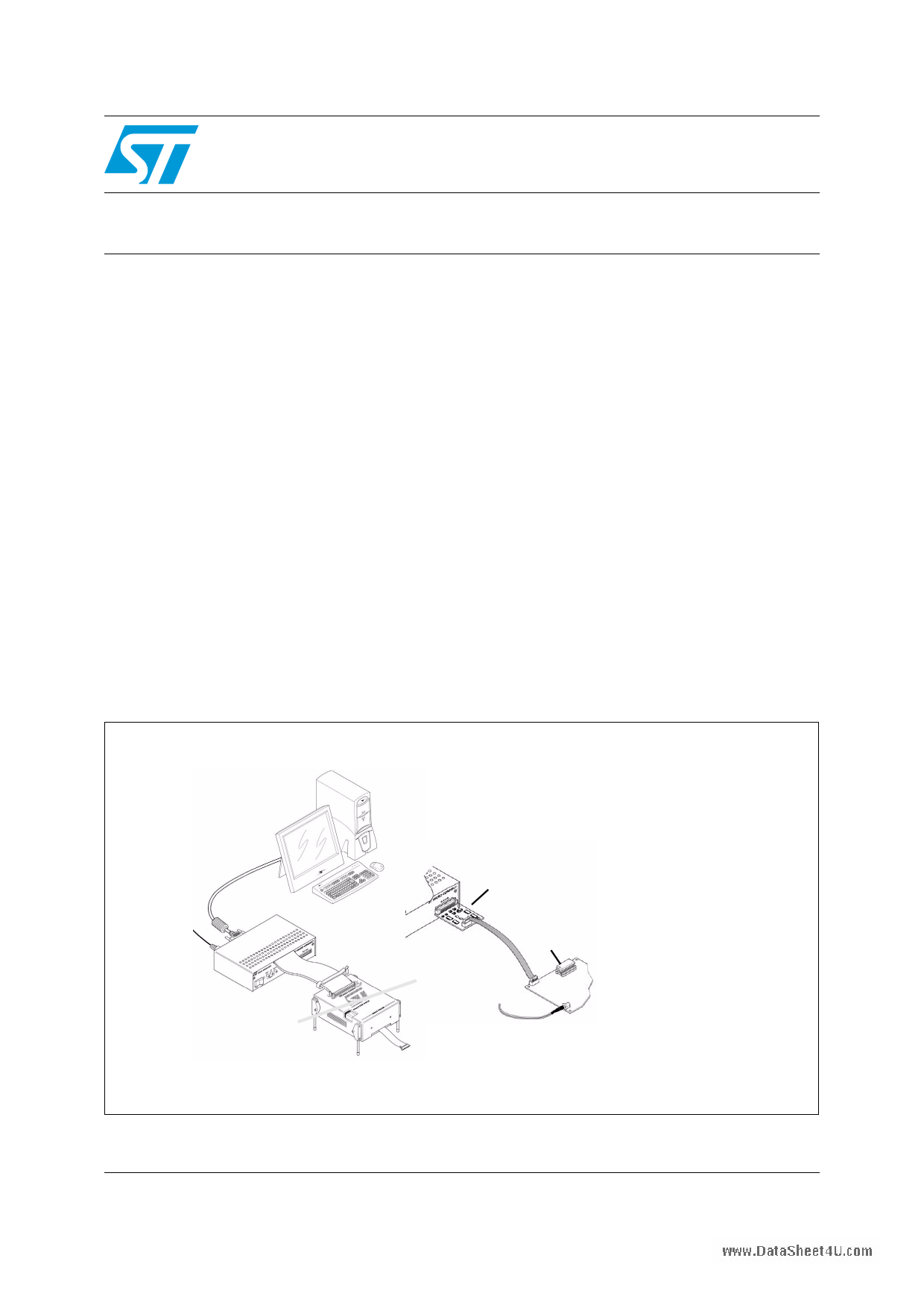
Figure 1. ST7-EMU3 emulator configurations
Host PC running
STVD7 or STVP7
Connects via Parallel,
USB or 10 MHz
Ethernet connection
ICC Add-on
Emulation configuration
STVD7
ST Micro Connect box
Probe
-or-
ST Micro Connect box
Probe
ST7
In-circuit communication
configuration
STVD7 or STVP7
ST Micro Connect box
ICC Add-on
ST7 in your application
March 2009
Rev 4
1/39
www.st.com
1 page 
www.DataSShTee7t-4EUM.coUm3 series emulator
Getting Started with ST7-EMU3
2 Getting Started with ST7-EMU3
Your ST7-EMU3 emulator can be configured for emulation, as well as in-circuit debugging
and programming of your ST7 microcontroller.
To help you get started, the following sections provide:
Section 1.1 – a checklist of components included with your emulator
Section 1.2 – quick set up instructions for the emulation configuration
Section 1.3 – quick set up instructions for the in-circuit communication configuration
2.1 Delivery check list
The ST7-EMU3 emulator comes with (refer to Figure 2):
1. One ST Micro Connect box.
2. One EMU3 probe containing a target emulation board (TEB) corresponding to the ST7
you wish to emulate.
3. One DC power supply for the ST Micro Connect box.
4. Two 80-wire flat cables and two ferrite clips.
5. Three trigger cables.
6. One 9-wire, analyzer-input cable.
7. One parallel cable and one USB cable for emulator-PC connection,
One DB9F/DB9M serial cable (not shown) for Ethernet configuration.
8. One ICC Add-on (STMC ICC board, ICC cable with HE10 connectors).
9. Device adapters (refer to the ST7xxxx-EMU3 Probe User Guide).
All ST7-EMU3 emulator s also come with the following documentation:
● This manual
● ST7xxxx-EMU3 Probe User Guide
● ST7 ASM Quick Reference Guide
● ST Product and Tool Selection Guide
● The Microcontroller Development Tools CD-ROM with all the software you need to run
your ST7-EMU3 emulator, including:
– The ST7 Visual Develop (STVD7) software with user manual in Adobe® Acrobat®
PDF format.
– The ST7 Visual Programmer (STVP7) software, which includes an online help file
to get you started.
– The ST7 Assembler-Linker software with user manual in Adobe® Acrobat® PDF
format.
– Software demonstration packages, including C compilers and toolchains by
Cosmic and Metrowerks.
● The ST Microcontrollers Mini-ROM with a presentation of the ST family of
microcontrollers.
5/39
5 Page 
www.DataSShTee7t-4EUM.coUm3 series emulator
Connectivity
3.2
3.2.1
USB port
Your EMU3 emulator supports USB connection in both the emulation and in-circuit
communication configurations, when using Windows® 98, Millenium, 2000 and XP®.
Connecting to the USB port
Figure 9. USB connection between ST Micro Connect box and PC
1 To USB port on PC
ST Micro Connect box
view of rear panel
3 Set the connection type in
STVD7 or STVP7
2 USB
connector
For USB port connections, plug the USB cable into the USB port of the ST Micro Connect
box (as shown in Figure 9) and connect the other end into the PC’s USB port. Once the
ST Micro Connect box is connected and powered-on for the first time, your PC will
automatically look for a USB device driver.
11/39
11 Page | ||
| Páginas | Total 30 Páginas | |
| PDF Descargar | [ Datasheet UM0034.PDF ] | |
Hoja de datos destacado
| Número de pieza | Descripción | Fabricantes |
| UM0034 | Getting Started | STMicroelectronics |
| Número de pieza | Descripción | Fabricantes |
| SLA6805M | High Voltage 3 phase Motor Driver IC. |
Sanken |
| SDC1742 | 12- and 14-Bit Hybrid Synchro / Resolver-to-Digital Converters. |
Analog Devices |
|
DataSheet.es es una pagina web que funciona como un repositorio de manuales o hoja de datos de muchos de los productos más populares, |
| DataSheet.es | 2020 | Privacy Policy | Contacto | Buscar |