|
|
|
PDF IRG4BC20FDPBF Data sheet ( Hoja de datos )
| Número de pieza | IRG4BC20FDPBF | |
| Descripción | INSULATED GATEBIPOLAR TRANSISTOR | |
| Fabricantes | International Rectifier | |
| Logotipo | ||
Hay una vista previa y un enlace de descarga de IRG4BC20FDPBF (archivo pdf) en la parte inferior de esta página. Total 11 Páginas | ||
|
No Preview Available !
www.datasheet4u.com
PD - 94906
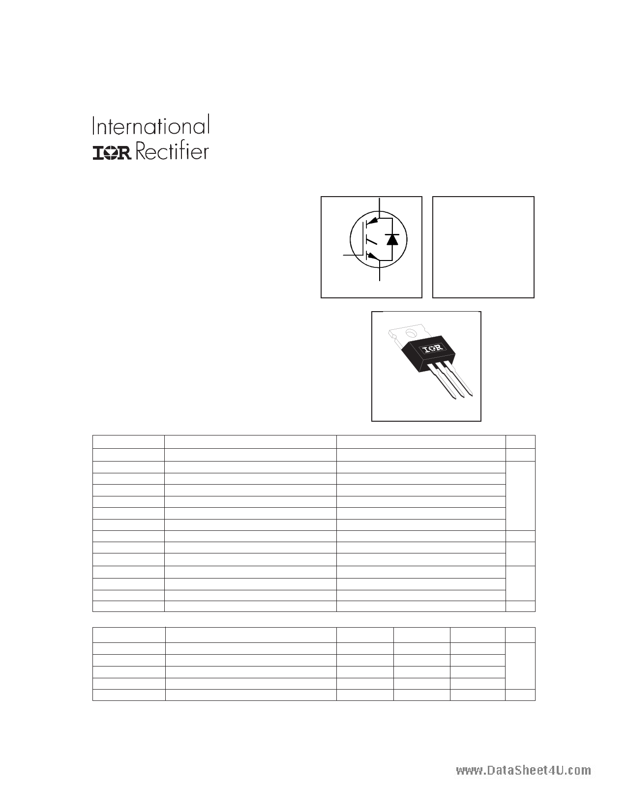
IRG4BC20FDPbF
INSULATED GATE BIPOLAR TRANSISTOR WITH ULTRAFAST
SOFT RECOVERY DIODE
Features
Fast: optimized for medium operating
C
frequencies ( 1-5 kHz in hard switching, >20
kHz in resonant mode).
Generation 4 IGBT design provides tighter
parameter distribution and higher efficiency than
Generation 3
G
IGBT co-packaged with HEXFREDTM ultrafast,
ultra-soft-recovery anti-parallel diodes for use in
bridge configurations
E
n-channel
Industry standard TO-220AB package
Lead-Free
Benefits
Generation -4 IGBTs offer highest efficiencies
available
IGBTs optimized for specific application conditions
HEXFRED diodes optimized for performance with
IGBTs. Minimized recovery characteristics require
less/no snubbing
Designed to be a "drop-in" replacement for equivalent
industry-standard Generation 3 IR IGBTs
Absolute Maximum Ratings
Fast CoPack IGBT
VCES = 600V
VCE(on) typ. = 1.66V
@VGE = 15V, IC = 9.0A
TO-220AB
VCES
IC @ TC = 25°C
IC @ TC = 100°C
ICM
ILM
IF @ TC = 100°C
IFM
VGE
PD @ TC = 25°C
PD @ TC = 100°C
TJ
TSTG
Parameter
Collector-to-Emitter Voltage
Continuous Collector Current
Continuous Collector Current
Pulsed Collector Current
Clamped Inductive Load Current
Diode Continuous Forward Current
Diode Maximum Forward Current
Gate-to-Emitter Voltage
Maximum Power Dissipation
Maximum Power Dissipation
Operating Junction and
Storage Temperature Range
Soldering Temperature, for 10 sec.
Mounting Torque, 6-32 or M3 Screw.
Max.
600
16
9.0
64
64
7.0
32
± 20
60
24
-55 to +150
300 (0.063 in. (1.6mm) from case)
10 lbfin (1.1 Nm)
Units
V
A
V
W
°C
Thermal Resistance
RθJC
RθJC
RθCS
RθJA
Wt
www.irf.com
Parameter
Junction-to-Case - IGBT
Junction-to-Case - Diode
Case-to-Sink, flat, greased surface
Junction-to-Ambient, typical socket mount
Weight
Min.
Typ.
0.50
2 (0.07)
Max.
2.1
3.5
80
Units
°C/W
g (oz)
1
12/23/03
1 page 
www.datasheet4u.com
1000
800
VCGiesE
=
=
0V,
Cge
+
f = 1MHz
Cgc , Cce
SHORTED
CCroeess
=
=
CCgcec
+
Cgc
600 Cies
400
200
0
1
Coes
Cres
10 100
VCE , Collector-to-Emitter Voltage (V)
Fig. 7 - Typical Capacitance vs.
Collector-to-Emitter Voltage
IRG4BC20FDPbF
20 VCC = 400V
I C = 9.0A
16
12
8
4
0
0 5 10 15 20 25 30
QG , Total Gate Charge (nC)
Fig. 8 - Typical Gate Charge vs.
Gate-to-Emitter Voltage
0.90 VCC = 480V
0.88
VGE
TJ
=
=
15V
25 °
C
IC = 9.0A
0.86
0.84
0.82
0.80
0.78
0
10 20 30 40
RG , Gate Resistance (OΩhm)
50
Fig. 9 - Typical Switching Losses vs. Gate
Resistance
www.irf.com
10 RG = 50OΩhm
VGE = 15V
VCC = 480V
1
IC = 18A
IC = 9.09AA
IC = 4.5A
0.1
-60 -40 -20 0 20 40 60 80 100 120 140 160
TJ, Junction Temperature ( °C )
Fig. 10 - Typical Switching Losses vs.
Junction Temperature
5
5 Page 
www.datasheet4u.com
Note: For the most current drawings please refer to the IR website at:
http://www.irf.com/package/
11 Page | ||
| Páginas | Total 11 Páginas | |
| PDF Descargar | [ Datasheet IRG4BC20FDPBF.PDF ] | |
Hoja de datos destacado
| Número de pieza | Descripción | Fabricantes |
| IRG4BC20FDPBF | INSULATED GATEBIPOLAR TRANSISTOR | International Rectifier |
| Número de pieza | Descripción | Fabricantes |
| SLA6805M | High Voltage 3 phase Motor Driver IC. |
Sanken |
| SDC1742 | 12- and 14-Bit Hybrid Synchro / Resolver-to-Digital Converters. |
Analog Devices |
|
DataSheet.es es una pagina web que funciona como un repositorio de manuales o hoja de datos de muchos de los productos más populares, |
| DataSheet.es | 2020 | Privacy Policy | Contacto | Buscar |