|
|
|
PDF SG6980 Data sheet ( Hoja de datos )
| Número de pieza | SG6980 | |
| Descripción | Single-Stage PFC Controller | |
| Fabricantes | Fairchild Semiconductor | |
| Logotipo | ||
Hay una vista previa y un enlace de descarga de SG6980 (archivo pdf) en la parte inferior de esta página. Total 18 Páginas | ||
|
No Preview Available !
Single-Stage PFC Controller
www.DataSheet4U.com
FEATURES OVERVIEW
Innovative switching-charge multiplier divider
Multi-vector control for improved PFC output
transient response
1:1 Synchronous switching with SYNC
Average current mode control
Remote on/off control
Power-on sequence control
Programmable PFC output-voltage control
Cycle-by-cycle current limiting
Over-voltage and under-voltage protections
Brownout and open-loop protections
Low start-up and operating current
APPLICATIONS
Active-PFC switching power supplies
TV and home appliances
Computer and telecom
Product Specification
SG6980
DESCRIPTION
The highly integrated SG6980 is designed for power
supplies with boost power-factor-correction (PFC).
It requires very few external components to achieve
desirable operation and includes versatile protections /
compensation. It is available in 16-pin DIP and SOP
packages. The innovative switching-charge multiplier
divider enhances the PFC circuit’s noise immunity. The
proprietary multi-vector control scheme provides a fast
transient response in a low-bandwidth PFC loop, in which
the overshoot and undershoot of the PFC voltage are
clamped. If the feedback loop is broken, SG6980 shuts off
to prevent extra-high voltage on output. The PFC gate
driver can be synchronized with external SYNC signal
and the switching noise can be reduced. During start-up,
the RDY (ready) is pulled low until the PFC output
voltage reaches the setting level. This signal can be used
to control the second forward stage for proper power-on
sequence. In addition, SG6980 provides complete
protection functions, such as brownout and RI open/short.
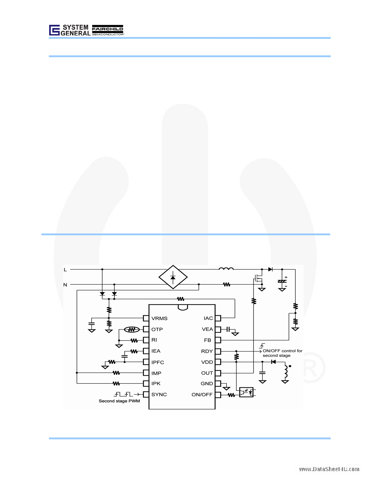
TYPICAL APPLICATION
SG6980
© System General Corp.
Version 1.0.1 (IAO33.0064.B0)
- 1 - www.sg.com.tw • www.fairchildsemi.com
September 17, 2007
1 page 
Product Specification
Single-Stage PFC Controller
www.DataSheet4U.com
SG6980
ABSOLUTE MAXIMUM RATING
Symbol
Parameter
Value
VVDD
IAC
VHigh
VLow
PD
DC Supply Voltage*
Input AC Current
OUT, SYNC, ON/OFF, RDY
Others
Power Dissipation
25
2
-0.3 to 25V
-0.3 to 7V
DIP
SOP
0.8
0.4
TJ
TA
TSTG
Rθj-C
Operating Junction Temperature
Operating Ambient Temperature Range
Storage Temperature RDY
Thermal resistance (Junction-to-Case)
+150
-20~+125
-55 to +150
DIP 36.70
SOP
37.76
TL
VESD,HBM
VESD,MM
Lead Temperature (Wave Soldering or IR, 10 Seconds)
ESD Capability, Human Body Model
ESD Capability, Machine Model
260
4
250
*All voltage values, except differential voltages, are given with respect to the network ground terminal.
Unit
V
mA
V
V
W
℃
℃
℃/W
℃
KV
V
*Stress beyond those listed under “ABSOLUTE MAXIMUM RATING” may cause permanent damage to the device.
ELECTRICAL CHARACTERISTICS
VDD=15V, TA=25°C unless otherwise noted.
VDD Section
Symbol
Parameter
VDD-OP
Continuously Operating Voltage
IDD-OP
I IC-OFF
Operating Current
Input Current
IDD-ST
Start-up Current
VDD-ON
VDD-OFF
VDD-OVP
Start Threshold Voltage
Minimum Operating Voltage
VDD Over-Voltage Protection with a
Debounce Time
tD-VDDOVP
Debounce Time of VDD OVP
Test Conditions
RI= 24KΩ,VDD = 15V; Gate Open
VON/OFF<VON ,VDD=25V
VDD<VDD-ON-0.16V
Min.
11.5
9
Typ.
4
25
10
12.5
10
Max.
20
5
35
20
13.5
11
Unit
V
mA
µA
µA
V
V
23.5 24.5 25.5 V
10 40 µs
Oscillator & Green-Mode Operation
Symbol
Parameter
FOSC
RI
PWM Frequency
Nominal RI Value
RIOPEN
RISHORT
Maximum RI Value for Protection
Maximum RI Value for Protection
Test Conditions
RI= 24KΩ
Min.
62
15
Typ.
65
200
2
Max.
68
40
Unit
KHz
KΩ
KΩ
KΩ
© System General Corp.
Version 1.0.1 (IAO33.0064.B0)
- 5 - www.sg.com.tw • www.fairchildsemi.com
September 17, 2007
5 Page 
Single-Stage PFC Controller
www.DataSheet4U.com
OPERATION DESCRIPTION
The highly integrated SG6980 is designed for a power
supply with boost PFC. It requires very few external
components to achieve high performance and includes
versatile protections / compensation.
The PFC function is implemented by average current
mode control. The patented switching-charge
multiplier-divider provides a high-degree of noise
immunity for the PFC circuit. This enables the PFC circuit
to operate over a much wider region. The proprietary
multi-vector output voltage control scheme provides a fast
transient response in a low-bandwidth PFC loop, in which
the overshoot and undershoot of the PFC voltage are
clamped. If the feedback loop is broken, the SG6980 shuts
off PFC to prevent extra-high voltage on output.
Programmable two-level high/low line compensation
optimizes THD performance.
In addition, SG6980 provides complete protection
functions, such as brownout and RI open/short.
Product Specification
SG6980
Line Voltage Detection (VRMS)
Figure 1 shows a resistive divider with low-pass filtering
for line-voltage detection on the VRMS pin. The VRMS
voltage is used for the PFC multiplier, brownout
protection, and RDY control.
For brownout protection, the SG6980 is disabled with
195ms delay time if the voltage VRMS drops below 0.8V.
For PFC multiplier and RDY control, please refer to
below sections for more detail.
Switching Frequency and Current
Sources
The switching frequency of SG6980 can be programmed
by the resistor RI connected between RI pin and GND.
The relationship is:
fPWM
=
1560
RI (kΩ)
( kHz )
-------------
(1)
For example, a 24kΩ resistor RI results in a 65kHz
switching frequency. Accordingly, constant current IT
flows through RI.
IT
=
1.2V (mA)
RI (kΩ)
----------------
(2)
IT is used to generate internal current reference.
If there is a SYNC signal input, the switching frequency is
defined by the SYNC signal. The SNYC frequency must
be larger than the programmed switching frequency,
less 6KHz.
FIG.1
PFC Output Voltage Control
For a universal input (90VAC ~ 264VAC) power supply
applying active boost PFC and forward as a second stage,
the output voltage of PFC is usually designed around 400V.
Vo = RA + RB × 3V ----
RB
(3)
© System General Corp.
Version 1.0.1 (IAO33.0064.B0)
FIG.2 Output Voltage Setting
- 11 -
www.sg.com.tw • www.fairchildsemi.com
September 17, 2007
11 Page | ||
| Páginas | Total 18 Páginas | |
| PDF Descargar | [ Datasheet SG6980.PDF ] | |
Hoja de datos destacado
| Número de pieza | Descripción | Fabricantes |
| SG6980 | Single-Stage PFC Controller | Fairchild Semiconductor |
| Número de pieza | Descripción | Fabricantes |
| SLA6805M | High Voltage 3 phase Motor Driver IC. |
Sanken |
| SDC1742 | 12- and 14-Bit Hybrid Synchro / Resolver-to-Digital Converters. |
Analog Devices |
|
DataSheet.es es una pagina web que funciona como un repositorio de manuales o hoja de datos de muchos de los productos más populares, |
| DataSheet.es | 2020 | Privacy Policy | Contacto | Buscar |