|
|
|
PDF LTC3528B Data sheet ( Hoja de datos )
| Número de pieza | LTC3528B | |
| Descripción | 1MHz Synchronous Step-Up DC/DC Converters | |
| Fabricantes | Linear Technology Corporation | |
| Logotipo | ||
Hay una vista previa y un enlace de descarga de LTC3528B (archivo pdf) en la parte inferior de esta página. Total 16 Páginas | ||
|
No Preview Available !
LTC3528/LTC3528B
1A, 1MHz Synchronous
Step-Up DC/DC Converters
in 3mm × 2mm DFN
FEATURES
DESCRIPTION
■ Delivers 3.3V at 200mA from a Single Alkaline/
NiMH Cell or 3.3V at 400mA from Two Cells
■ VIN Start-Up Voltage: 700mV
■ 1.6V to 5.25V VOUT Range
www.DataSh■eetU4Up.ctoom94% Efficiency
■ Output Disconnect
■ 1MHz Fixed Frequency Operation
■ VIN > VOUT Operation
■ Integrated Soft-Start
■ Current Mode Control with Internal Compensation
■ Burst Mode® Operation with 12μA Quiescent Current
(LTC3528)
■ Low Noise PWM Operation (LTC3528B)
■ Internal Synchronous Rectifier
■ Logic Controlled Shutdown: <1μA
■ Anti-Ringing Control
■ Low Profile (3mm × 2mm × 0.75mm) DFN Package
APPLICATIONS
■ Medical Instruments
■ Flash-Based MP3 Players
■ Noise Canceling Headphones
■ Wireless Mice
■ Bluetooth Headsets
The LTC®3528/LTC3528B are synchronous, fixed frequency
step-up DC/DC converters with output disconnect. High
efficiency synchronous rectification, in addition to a 700mV
start-up voltage and operation down to 500mV once
started, provides longer run-time for single or multiple
cell battery-powered products.
A switching frequency of 1MHz minimizes solution foot-
print by allowing the use of tiny, low profile inductors and
ceramic capacitors. The current mode PWM is internally
compensated, simplifying the design process. The LTC3528
enters Burst Mode operation at light loads, while the
LTC3528B features continuous switching at light loads.
Anti-ringing circuitry reduces EMI by damping the inductor
in discontinuous mode. Additional features include a low
shutdown current, open-drain power good output, short-
circuit protection and thermal overload protection.
The LTC3528/LTC3528B are offered in an 8-lead 3mm ×
2mm × 0.75mm DFN package.
, LT, LTC, LTM and Burst Mode are registered trademarks of Linear Technology
Corporation. All other trademarks are the property of their respective owners.
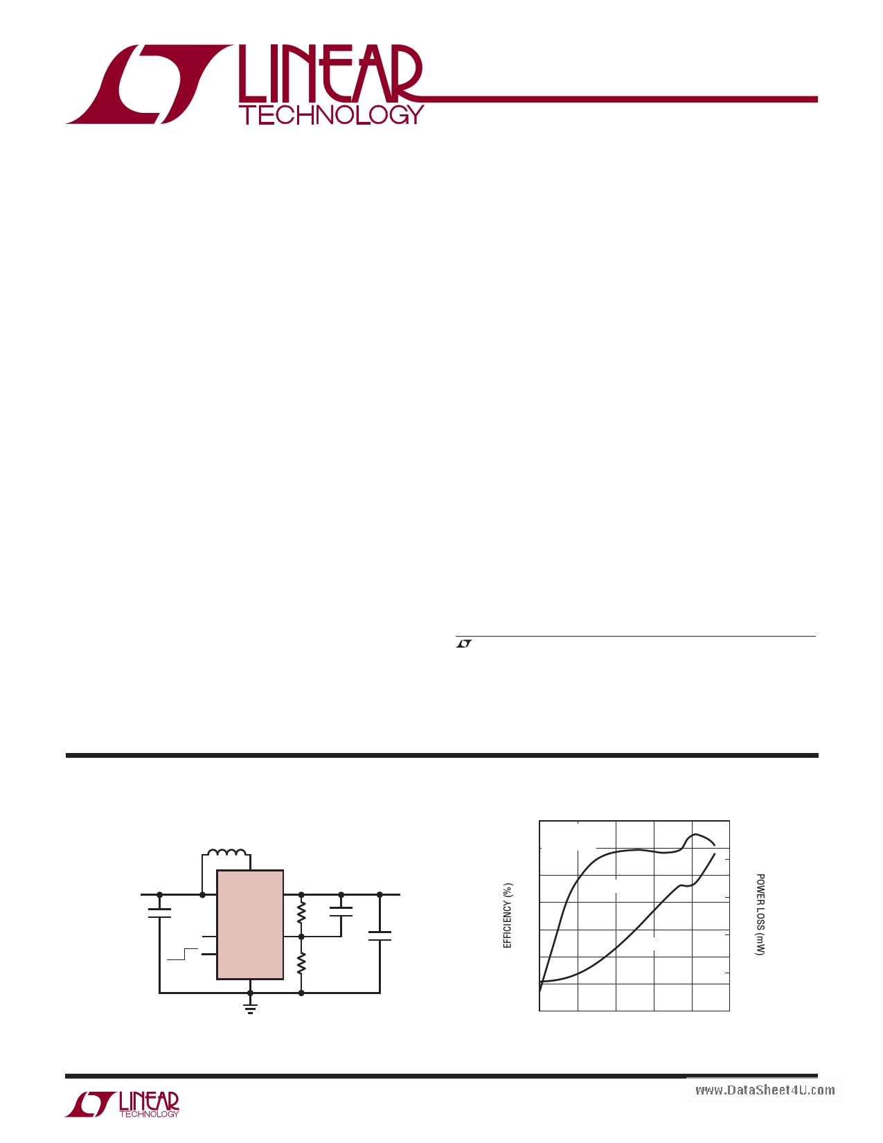
TYPICAL APPLICATION
4.7μH
VIN
1.8V TO 3.2V
4.7μF
OFF ON
SW
VIN VOUT
LTC3528
PGOOD FB
SHDN
GND
499k
287k
33pF
VOUT
3.3V
400mA
10μF
3528 TA01a
Efficiency and Power Loss
100
VOUT = 3.3V
90 VIN = 2.4V
80
EFFICIENCY
70
1000
100
10
60 1
POWER LOSS
50
0.1
40
30
0.01
0.1 1 10 100
LOAD CURRENT (mA)
0.01
1000
3528 TA01b
3528fa
1
1 page 
LTC3528/LTC3528B
TYPICAL PERFORMANCE CHARACTERISTICS (TA = 25°C unless otherwise noted)
Burst Mode Threshold Current
vs VIN
60
VOUT = 5V
40
www.DataSheet4U.com
20
RISING
FALLING
0
1234
VIN (V)
3528 G11
Oscillator Frequency Change
vs Temperature
5
NORMALIZED TO 25°C
4
3
2
1
0
–1
–2
–3
–4
–5
–50 –30 –10 10 30 50 70 90
TEMPERATURE (°C)
3528 G14
Start-Up Voltage vs Temperature
850
800
750
700
650
600
–50 –30 –10 10 30 50
TEMPERATURE (°C)
70 90
3528 G17
Oscillator Frequency Change
vs VOUT
0.50
0.25 NORMALIZED TO VOUT = 3V
0
–0.25
–0.50
–0.75
–1.00
–1.25
–1.50
–1.75
–2.00
–2.25
1.5 2 2.5 3 3.5 4 4.5 5
VOUT (V)
3528 G12
RDS(ON) vs VOUT
450
400
350
300
PMOS
250
200
NMOS
150
100
1.5 2
2.5 3 3.5 4
VOUT (V)
4.5 5
3528 G13
RDS(ON) Change vs Temperature
30
VFB vs Temperature
1.200
20
1.195
10
1.190
0
1.185
–10
–20
–50 –30 –10 10 30 50
TEMPERATURE (°C)
70 90
3528 G15
1.180
–50 –30 –10 10 30 50
TEMPERATURE (°C)
70 90
3528 G16
Burst Mode Quiescent Current vs
VOUT (LTC3528)
13.5
VIN = 1.2V
12.5
Fixed Frequency VOUT Ripple and
Inductor Current Waveforms
VOUT
20mV/DIV
IL
200mA/DIV
11.5
10.5
1
23
VOUT (V)
45
3528 G18
VIN = 1.2V
VOUT = 3.3V
COUT = 22μF
CFF = 33pF
IOUT = 100mA
2μs/DIV
3528 G19
3528fa
5
5 Page 
LTC3528/LTC3528B
APPLICATIONS INFORMATION
The inductor current ripple is typically set for 20% to
40% of the maximum inductor current. High frequency
ferrite core inductor materials reduce frequency depen-
dent power losses compared to cheaper powdered iron
types, improving efficiency. The inductor should have low
ESR (series resistance of the windings) to reduce the I2R
power losses, and must be able to handle the peak induc-
tor current without saturating. Molded chokes and some
www.DataShceheti4pUi.ncodmuctors usually do not have enough core area to
support the peak inductor currents of 1.5A seen on the
LTC3528/LTC3528B. To minimize radiated noise, use a
shielded inductor. See Table 1 for suggested components
and suppliers.
Table 1. Recommended Inductors
VENDOR
PART/STYLE
Coilcraft
(847) 639-6400
www.coilcraft.com
LPO2506, MSS5131
MSS6122, MOS6020
ME3220, DO1608C
1812PS
Coiltronics
SD14, SD18, SD20
SD25, SD52
Sumida
(847) 956-0666
www.sumida.com
CD43
CDC5D23B
CDRH5D18
CR43
TDK VLP, VLF
VLCF, SLF
Toko
(408) 432-8282
www.tokoam.com
D53, D63
D73, D75
Wurth
(201) 785-8800
www.we-online.com
WE-TPC type M, MH
Output and Input Capacitor Selection
Low ESR (equivalent series resistance) capacitors should
be used to minimize the output voltage ripple. Multilayer
ceramic capacitors are an excellent choice as they have
extremely low ESR and are available in small footprints.
A 10μF to 22μF output capacitor is sufficient for most ap-
plications. Values larger than 22μF may be used to obtain
extremely low output voltage ripple and improve transient
response. X5R and X7R dielectric materials are preferred
for their ability to maintain capacitance over wide voltage
and temperature ranges. Y5V types should not be used.
The internal loop compensation of the LTC3528/LTC3528B
is designed to be stable with output capacitor values of 10μF
or greater. Although ceramic capacitors are recommended,
low ESR tantalum capacitors may be used as well.
A small ceramic capacitor in parallel with a larger tantalum
capacitor may be used in demanding applications which
have large load transients. Another method of improving
the transient response is to add a small feed-forward
capacitor across the top resistor of the feedback divider
(from VOUT to FB). A typical value of 33pF will generally
suffice.
Low ESR input capacitors reduce input switching noise
and reduce the peak current drawn from the battery. It
follows that ceramic capacitors are also a good choice
for input decoupling and should be located as close as
possible to the device. A 10μF input capacitor is sufficient
for most applications. Larger values may be used without
limitations. Table 2 shows a list of several ceramic capaci-
tor manufacturers. Consult the manufacturers directly for
detailed information on their selection of ceramic parts.
Table 2. Capacitor Vendor Information
SUPPLIER
PHONE
AVX (803) 448-9411
Murata
(714) 852-2001
Taiyo-Yuden
(408) 573-4150
TDK (847) 803-6100
WEBSITE
www.avxcorp.com
www.murata.com
www.t-yuden.com
www.component.tdk.com
3528fa
11
11 Page | ||
| Páginas | Total 16 Páginas | |
| PDF Descargar | [ Datasheet LTC3528B.PDF ] | |
Hoja de datos destacado
| Número de pieza | Descripción | Fabricantes |
| LTC3528 | 1MHz Synchronous Step-Up DC/DC Converters | Linear Technology Corporation |
| LTC3528-2 | 2MHz Synchronous Step-Up DC/DC Converter | Linear |
| LTC3528B | 1MHz Synchronous Step-Up DC/DC Converters | Linear Technology Corporation |
| LTC3528B-2 | 2MHz Synchronous Step-Up DC/DC Converter | Linear |
| Número de pieza | Descripción | Fabricantes |
| SLA6805M | High Voltage 3 phase Motor Driver IC. |
Sanken |
| SDC1742 | 12- and 14-Bit Hybrid Synchro / Resolver-to-Digital Converters. |
Analog Devices |
|
DataSheet.es es una pagina web que funciona como un repositorio de manuales o hoja de datos de muchos de los productos más populares, |
| DataSheet.es | 2020 | Privacy Policy | Contacto | Buscar |