|
|
|
PDF ISL88022 Data sheet ( Hoja de datos )
| Número de pieza | ISL88022 | |
| Descripción | (ISL88021 / ISL88022) Triple Voltage Monitor | |
| Fabricantes | Intersil Corporation | |
| Logotipo | ||
Hay una vista previa y un enlace de descarga de ISL88022 (archivo pdf) en la parte inferior de esta página. Total 7 Páginas | ||
|
No Preview Available !
®
Data Sheet
ISL88021, ISL88022
September 18, 2006
FN8226.1
Triple Voltage Monitor with Adjustable
Power-On-Reset and Undervoltage/
Overvoltage Monitoring Capability
The ISL88021 and ISL88022 family of devices are
customizable triple voltage-monitoring supervisors that
assert a reset if any of the monitored voltages becomes
non-compliant. They offer popular functions such as
Power-On-Reset timing control with both RESET and
RESET outputs, Supply Voltage Supervision, both under or
overvoltage detection, and Manual Reset assertion. By
offering these features in a small 8 Ld MSOP package, the
ISL88021 and ISL88022 can lower system cost, reduce
board space requirements and increase the reliability of
systems.
Applying a voltage to VDD activates the Power-On-Reset
circuit which holds RESET low for an adjustable period of
time. This allows the power supply and system oscillator to
stabilize before the processor can execute code.
Low VDD detection circuitry protects the user’s system from
low voltage conditions, resetting the system when VDD falls
below its minimum preset voltage threshold VTH1. Reset
remains
www.DataSheet4U.com
asserted
until
VDD
returns
to
its
proper
operating
level and stabilizes. Two additional voltage monitoring
inputs, V2MON (preset) and V3MON (adjustable), monitor
other supplies to provide reliable system operation.
The ISL88021 V3MON input monitors for undervoltage (UV)
conditions whereas the ISL88022 V3MON input allows
monitoring for overvoltage (OV) conditions. The monitored
voltage on V3MON on either device is compared via a
resistor divider to a 600mV internal reference. Hence, any
voltage more or less positive than this reference can be
accurately monitored to meet specific system level
requirements or to fine-tune the threshold for applications
requiring higher precision.
These devices also let users increase the Power-On-Reset
time-out delay by connecting a capacitor between CPOR and
ground. This lengthens the period of an internal clock
counter thereby increasing the time between voltage
compliance and reset outputs signaling.
A manual reset input provides debounce circuitry for
minimum reset component count.
Features
• Triple Voltage Monitor and Reset Assertion
• Low VDD Detection and Reset Assertion
- Adjustable Reset Threshold Voltages
- 0.6V ±6mV Over -40°C to +85°C
- Reset Signal Valid to VDD = 1V
• 140ms Minimum Reset Pulse Delay that is Customizable
Using an External Capacitor
• Both RST and RST Outputs Available
• Undervoltage/Overvoltage Monitoring Capability
• Low 20µA Consumption
• Small 8 Ld MSOP Package
• Pb-Free Plus Anneal Available (RoHS Compliant)
Applications
• Process Control Systems
• Intelligent Instruments
• Embedded Control Systems
• Computer Systems
• Portable/Battery-Powered Equipment
• Multi-Voltage Systems
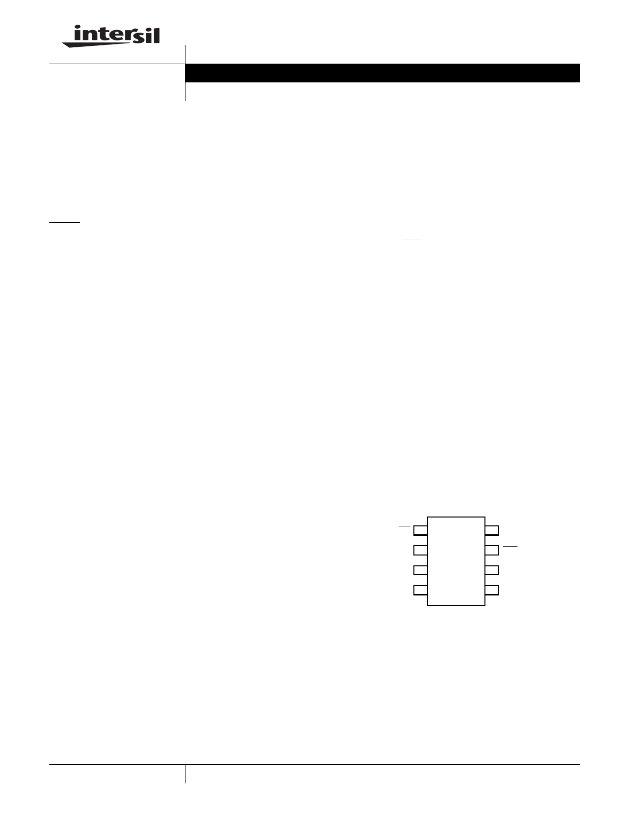
Pinout
ISL88021, ISL88022
(8 LD MSOP)
TOP VIEW
MR
VDD
V2MON
GND
1
2
3
4
8 RST
7 RST
6 CPOR
5 V3MON
1 CAUTION: These devices are sensitive to electrostatic discharge; follow proper IC Handling Procedures.
1-888-INTERSIL or 1-888-468-3774 | Intersil (and design) is a registered trademark of Intersil Americas Inc.
Copyright Intersil Americas Inc. 2006. All Rights Reserved
All other trademarks mentioned are the property of their respective owners.
1 page 
ISL88021, ISL88022
Manual Reset
The manual reset input (MR) allows the user to trigger a reset
by using a push-button switch or by signaling that pin low. The
MR input is an active low debounced input. By connecting a
push-button directly from MR to ground, the designer adds
manual system reset capability. Reset is asserted if the MR pin
is pulled low to less than 100mV for 1µs or longer while the
push-button is closed or a reset is signaled. After MR is
released, the reset outputs remain asserted for tPOR. MR input
has an internal 20kΩ pull up resistor provided.
Figure 3 illustrates a typical application diagram for either IC
showing both reset outputs being used along with both a
manual and signalled reset configuration. The VDD and
V2MON thresholds are preset whereas the V3MON is capable
of UV (ISL88021) or OV (ISL88022) monitoring of a voltage
greater than or less than 0.6V, respectively.
TO DISPLAY
3.3V - 5V
1.8V - 3.3V
VDD
V2MON
RST
RST
MR
ISL88021
ISL88022
TO µP
RESET
PB SIGNAL
VMON > 0.6V
V3MON
CPOR
GND
ISL88021IU8HFZ
ISL88022IU8HFZ
FIGURE 3. TYPICAL APPLICATION DIAGRAM
Application Considerations
Follow good decoupling practices to prevent transients from
causing unwanted reset signaling due to switching noises
and short duration droops.
When using the CPOR pin, reduce layout stray capacitance
on this pin to minimize effect on tPOR timing. If no PCB
CPOR pad is patterned, the tPOR can be 160ms.
Using the ISL88021_22EVAL1 Platform
The ISL88021_22EVAL1 board is designed to provide both
immediate functional assessment and flexibility to the user.
Both ICs are the ‘HF’ variant having a VDD Vth of 4.64V, a
V2MON Vth of 3.09V and V3MON Vth of 0.6V. The top IC
position is the ISL88021 and is configured to monitor for
undervoltage (UV) compliance of a 5V, 3.3V and a 2.5V and
signaling the RESET and RESET outputs. The bottom
position is the ISL88022 variant, which is configured to
measure a 3.3V overvoltage (OV) in addition to UV on both
the 5V and 3.3V supplies. RESET and RESET is asserted for
at least tPOR when these voltage go out of range. In both
cases V3MON interfaces with the monitored supply via a
simple resistor divider for comparison to the internal 0.6V
reference. A Manual Reset (MR) input is provided on both
ICs and is invoked by pulling this input LOW.
5
FIGURE 4. ISL88021_22EVAL1 SCHEMATIC AND PHOTO
MONITORED VOLTAGE RISING AND FALLING RAMP
THROUGH THE PROGRAMMED UV AND OV THRESHOLDS
RESET# RESPONDING TO
MONITORED VOLTAGE. CPOR
PIN IS OPEN, tPOR = 150ms
FIGURE 5. ISL88022EVAL1 3.3V UV AND OV DETECTION
FN8226.1
September 18, 2006
5 Page | ||
| Páginas | Total 7 Páginas | |
| PDF Descargar | [ Datasheet ISL88022.PDF ] | |
Hoja de datos destacado
| Número de pieza | Descripción | Fabricantes |
| ISL88021 | (ISL88021 / ISL88022) Triple Voltage Monitor | Intersil Corporation |
| ISL88022 | (ISL88021 / ISL88022) Triple Voltage Monitor | Intersil Corporation |
| Número de pieza | Descripción | Fabricantes |
| SLA6805M | High Voltage 3 phase Motor Driver IC. |
Sanken |
| SDC1742 | 12- and 14-Bit Hybrid Synchro / Resolver-to-Digital Converters. |
Analog Devices |
|
DataSheet.es es una pagina web que funciona como un repositorio de manuales o hoja de datos de muchos de los productos más populares, |
| DataSheet.es | 2020 | Privacy Policy | Contacto | Buscar |