|
|
|
PDF ISL6540A Data sheet ( Hoja de datos )
| Número de pieza | ISL6540A | |
| Descripción | Single-Phase Buck PWM Controller | |
| Fabricantes | Intersil Corporation | |
| Logotipo | ||
Hay una vista previa y un enlace de descarga de ISL6540A (archivo pdf) en la parte inferior de esta página. Total 20 Páginas | ||
|
No Preview Available !
®
Data Sheet
March 12, 2007
ISL6540A
FN6288.2
Single-Phase Buck PWM Controller with
Integrated High Speed MOSFET Driver
and Pre-Biased Load Capability
The ISL6540A is an improved version of the ISL6540
single-phase voltage-mode PWM controller with input voltage
feedforward compensation to maintain a constant loop gain for
optimal transient response, especially for applications with a
wide input voltage range. Its integrated high speed
synchronous rectified MOSFET drivers and other sophisticated
features provide complete control and protection for a DC/DC
converter with minimum external components, resulting in
minimum cost and less engineering design efforts.
The output voltage of the converter can be precisely regulated
with an internal reference voltage of 0.591V, and has an
improved system tolerance of ±0.68% over commercial
temperature and line load variations. An external voltage can
be used in place of the internal reference for voltage
tracking/DDR applications.
The ISL6540A has an internal linear regulator or external linear
regulator drive options for applications with only a single supply
rail. The internal oscillator is adjustable from 250kHz to 2MHz.
The integrated voltage margining, programmable pre-biased
soft-start, differential remote sensing amplifier, and
programmable input voltage POR features enhance the
ISL6540A value.
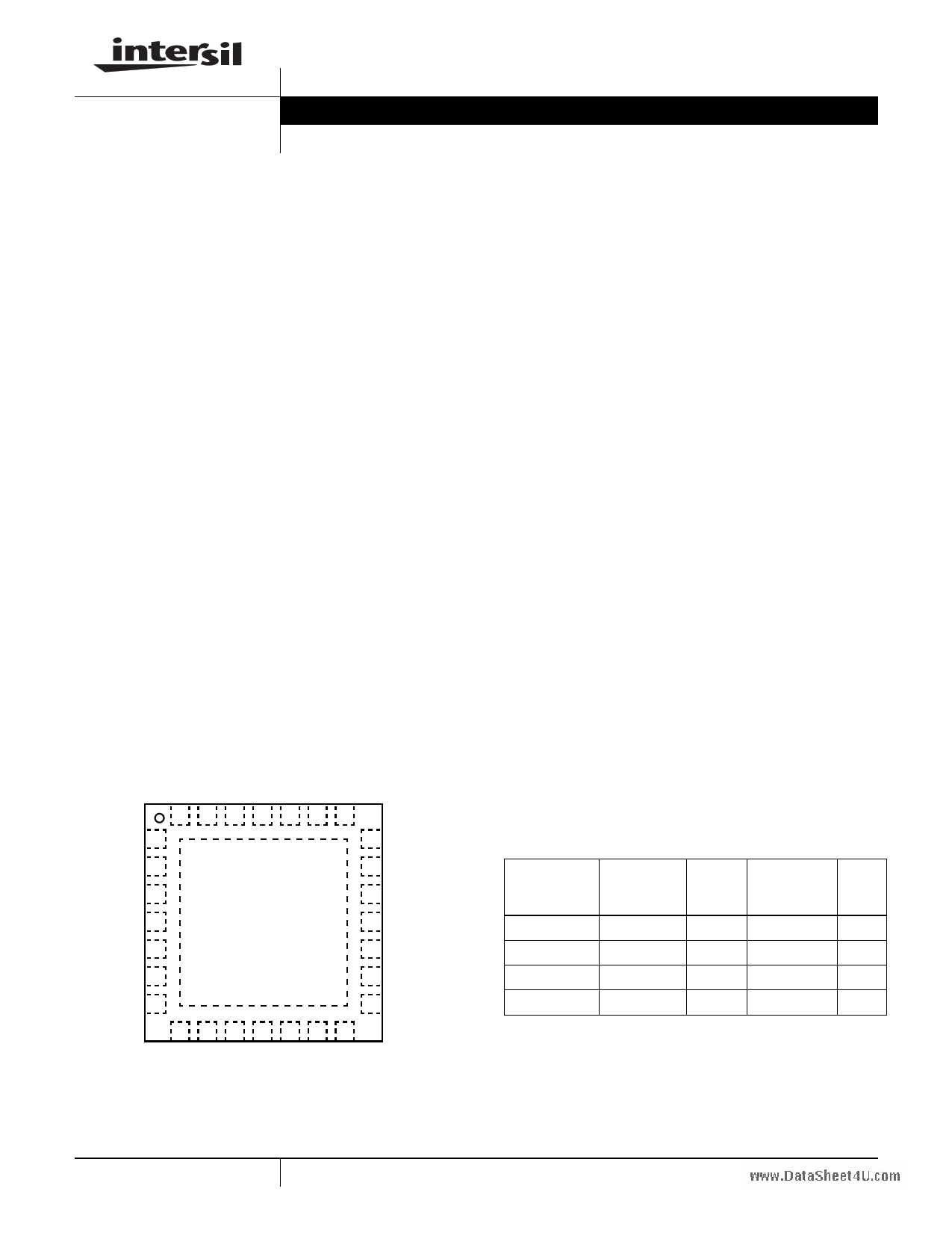
Pinout
ISL6540A
(28 LD 5x5 QFN)
TOP VIEW
28 27 26 25 24 23 22
VSEN+ 1
21 BOOT
VSEN- 2
20 UGATE
REFOUT 3
REFIN 4
SS 5
GND
BOTTOM
SIDE PAD
19 PHASE
18 PGND
17 LGATE
OFS+ 6
16 PVCC
OFS- 7
15 LINDRV
8 9 10 11 12 13 14
Features
• VIN and Power Rail Operation from +3.3V to +20V
• Fast Transient Response - 0 to 100% Duty Cycle
- 15MHz Bandwidth Error Amplifier with 6V/μs Slew Rate
- Voltage-Mode PWM Leading and Trailing-Edge
Modulation Control
- Input Voltage Feedforward Compensation
• 2.9V to 5.5V High Speed 2A/4A MOSFET Gate Drivers
- Tri-state for Power Stage Shutdown
• Internal Linear Regulator (LR) - 5.5V Bias from VIN
• External LR Drive for Optimal Thermal Performance
• Voltage Margining with Independently Adjustable Upper and
Lower Settings for System Stress Testing & Over Clocking
• Reference Voltage I/O for DDR/Tracking Applications
• Improved 0.591V Internal Reference with Buffered Output
- ±0.68%/±1.0% Over Commercial/Industrial Range
• Source and Sink Overcurrent Protections
- Low- and High-Side MOSFET rDS(ON) Sensing
• Overvoltage and Undervoltage Protections
• Small Converter Size - QFN package
• Oscillator Programmable from 250kHz to 2MHz
• Differential Remote Voltage Sensing with Unity Gain
• Programmable Soft-Start with Pre-Biased Load Capability
• Power Good Indication with Programmable Delay
• EN Input with Voltage Monitoring Capability
• Pb-Free Plus Anneal Available (RoHS Compliant)
Applications
• Power Supply for some Microprocessors and GPUs
• Wide and Narrow Input Voltage Range Buck Regulators
• Point of Load Applications
• Low-Voltage and High Current Distributed Power Supplies
Ordering Information
PART
NUMBER*
(Note)
PART
MARKING
TEMP.
RANGE
(°C)
PACKAGE PKG.
(Pb-Free) DWG. #
ISL6540ACRZ ISL6540ACRZ 0 to +70 28 Ld 5x5 QFN L28.5x5
ISL6540ACRZA ISL6540ACRZ 0 to +70 28 Ld 5x5 QFN L28.5x5
ISL6540AIRZ ISL6540AIRZ -40 to +85 28 Ld 5x5 QFN L28.5x5
ISL6540AIRZA ISL6540AIRZ -40 to +85 28 Ld 5x5 QFN L28.5x5
*Add “-T” suffix for tape and reel.
NOTE: Intersil Pb-free plus anneal products employ special Pb-free
material sets; molding compounds/die attach materials and 100% matte
tin plate termination finish, which are RoHS compliant and compatible with
both SnPb and Pb-free soldering operations. Intersil Pb-free products are
MSL classified at Pb-free peak reflow temperatures that meet or exceed
the Pb-free requirements of IPC/JEDEC J STD-020.
1 CAUTION: These devices are sensitive to electrostatic discharge; follow proper IC Handling Procedures.
1-888-INTERSIL or 1-888-468-3774 | Intersil (and design) is a registered trademark of Intersil Americas Inc.
Copyright Intersil Americas Inc. 2006, 2007. All Rights Reserved
All other trademarks mentioned are the property of their respective owners.
1 page 
ISL6540A
Typical Application III (Dual Data Rate I or II)
VDDQ
1.8V or 2.5V
5V
CVFF
REN1
RVFF
CF1
VIN
VFF
EN
LIN
RCC
DBOOT
CF2
VCC
PVCC
BOOT
HSOC
RHSOC
REN2
CF4
1K
15nF
REFIN
REFOUT
1K DIMM
PG
CPG_DLY
PG_DLY
RFS
FS
ISL6540A
UGATE
CHSOC
PHASE
LGATE
PGND
LSOC
RLSOC
COMP CLSOC
CHFIN
Q1
Q2
CBIN
CBOOT
LOUT
CHFOUT
ROFS+
MARCTRL
OFS+
RMARG
ROFS-
OFS-
CSS
SS
ZFB
C1
FB
VMON
VSEN+
C2
R2
VSEN-
C3 R3
R1 ZIN
CSEN
RFB
LINDRV GND GND
VTT
1.25V (DDR I)
0.9V (DDR II)
CBOUT
5 FN6288.2
March 12, 2007
5 Page 
ISL6540A
Functional Description
Initialization
The ISL6540A automatically initializes upon receipt of power
without requiring any special sequencing of the input
supplies. The Power-On Reset (POR) function continually
HIGH = ABOVE POR; LOW = BELOW POR
VCC POR
VFF POR
PVCC POR
EN POR
AND
SOFT-START
FIGURE 1. SOFT-START INITIALIZATION LOGIC
monitors the input supply voltages (PVCC, VFF, VCC) and
the voltage at the EN pin. Assuming the EN pin is pulled to
above ~0.50V, the POR function initiates soft-start operation
after all input supplies exceed their POR thresholds.
VIN
RUP
VREF
Sys_Enable
RDOWN
IEN_HYS=10μA
RUP
=
V-----E----N----_---H----Y---S--
I E N _HYS
RDOWN
=
-------R-----U----P-----•----V----E----N-----_---R---E----F--------
VEN_FTH – VEN_REF
VEN_FTH = VEN_RTH – VEN_HYS
FIGURE 2. ENABLE POR CIRCUIT
With all input supplies above their POR thresholds, driving
the EN pin above 0.50V initiates a soft-start cycle. In addition
to normal TTL logic, the enable pin can be used as a voltage
monitor with programmable hysteresis through the use of the
internal 10μA sink current and an external resistor divider.
This feature is especially designed for applications that have
input rails greater than a 3.3V and require a specific input rail
POR and Hysteresis levels for better undervoltage
protection. Consider for a 12V application choosing
RUP = 100kΩ and RDOWN = 5.76kΩ there by setting the
rising threshold (VEN_RTH) to ~10V and the falling threshold
(VEN_FTH) to ~9V, for 1V of hysteresis (VEN_HYS). Care
should be taken to prevent the voltage at the EN pin from
exceeding VCC when using the programmable UVLO
functionality.
Soft-Start
The POR function activates the internal 37μA OTA which
begins charging the external capacitor (CSS) on the SS pin to a
target voltage of VCC. The ISL6540A’s soft-start logic
continues to charge the SS pin until the voltage on COMP
exceeds the bottom of the oscillator ramp, at which point, the
driver outputs are enabled, with the low side MOSFET first
being held low for 200ns to provide for charging of the bootstrap
capacitor. Once the driver outputs are enabled, the OTA’s target
voltage is then changed to the margined (if margining is being
used) reference voltage (VREF_MARG), and the SS pin is
ramped up or down accordingly. This method reduces startup
surge currents due to a pre-charged output by inhibiting
regulator switching until the control loop enters its linear region.
By ramping the positive input of the error amplifier to VCC and
then to VREF_MARG, it is even possible to mitigate surge
currents from outputs that are pre-charged above the set output
voltage. As the SS pin connects directly to the non-inverting
input of the error amplifier, noise on this pin should be kept to a
minimum through careful routing and part placement. To
prevent noise injection into the error amplifier the SS capacitor
should be located within 150 mils of the SS and GND pins.
Soft-start is declared done when the drivers have been enabled
and the SS pin is within ±3mV of VREF_MARG.
VMON
+15%
+9%
VREF_MARG
-9%
-15%
GOOD
GOOD
UV OV UV
FIGURE 3. UNDERVOLTAGE-OVERVOLTAGE WINDOW
TPG_DLY = CPG_DLY ⋅ 1-2---.1--4--μ-9---A-V--
Power Good
The power good comparator references the voltage on the
soft-start pin to prevent accidental tripping during margining.
The trip points are shown on Figure 3. Additionally, power
good will not be asserted until after the completion of the
soft-start cycle. A 0.1μF capacitor at the PG_DLY pin will add
an additional ~7ms delay to the assertion of power good.
PG_DLY does not delay the de-assertion of power good.
Under and Overvoltage Protection
The Undervoltage (UV) and Overvoltage (OV) protection
circuitry compares the voltage on the VMON pin with the
reference that tracks with the margining circuitry to prevent
accidental tripping. UV and OV functionality is not enabled
until the end of soft-start.
11 FN6288.2
March 12, 2007
11 Page | ||
| Páginas | Total 20 Páginas | |
| PDF Descargar | [ Datasheet ISL6540A.PDF ] | |
Hoja de datos destacado
| Número de pieza | Descripción | Fabricantes |
| ISL6540 | Single-Phase Buck PWM Controller | Intersil Corporation |
| ISL6540A | Single-Phase Buck PWM Controller | Intersil Corporation |
| Número de pieza | Descripción | Fabricantes |
| SLA6805M | High Voltage 3 phase Motor Driver IC. |
Sanken |
| SDC1742 | 12- and 14-Bit Hybrid Synchro / Resolver-to-Digital Converters. |
Analog Devices |
|
DataSheet.es es una pagina web que funciona como un repositorio de manuales o hoja de datos de muchos de los productos más populares, |
| DataSheet.es | 2020 | Privacy Policy | Contacto | Buscar |