|
|
|
PDF IR2159 Data sheet ( Hoja de datos )
| Número de pieza | IR2159 | |
| Descripción | (IR2159 / IR21591) DIMMING BALLAST CONTROL IC | |
| Fabricantes | International Rectifier | |
| Logotipo | ||
Hay una vista previa y un enlace de descarga de IR2159 (archivo pdf) en la parte inferior de esta página. Total 25 Páginas | ||
|
No Preview Available !
www.DataSheet4U.com
Preliminary Data Sheet No. PD60169-D
IR2159(S)
IR21591(S)
DIMMING BALLAST CONTROL IC
Features
• Ballast control and half-bridge driver in one IC
• Transformer-less lamp power sensing
• Closed-loop lamp power control
• Closed-loop preheat current control
• Programmable preheat time
• Programmable preheat current
• Brown-out protection
• Automatic restart
• Micro-power startup
• Zener clamped Vcc
• Over-temperature protection
• 16-pin DIP and SOIC package types
• Programmable ignition-to-dim time
• 0.5 to 5VDC dimming control input
Parameter
IR2159 IR21591
• Min and max lamp power adjustments
• Programmable minimum frequency
• Internal current sense blanking
• Full lamp fault protection
Deadtime
Frequency
Range
1.8us
See
Graph 3
1.0us
See
Graph 4
Description
Packages
Description: The IR2159/IR21591 are complete dimming ballast controllers and 600V
half-bridge drivers all in one IC. The architecture includes phase control for trans-
former-less lamp power sensing and regulation which minimizes changes needed to
adapt non-dimming ballasts for dimming. Externally programmable features such as
preheat time and current, ignition-to-dim time, and a complete dimming interface with
minimum and maximum settings provide a high degree of flexibility for the ballast
design engineer. Protection from failure of a lamp to strike, filament failures, thermal
overload, or lamp failure during normal operation, as well as an automatic restart
function, have been included in the design. The heart of this control IC is a voltage-
controlled oscillator with externally programmable minimum frequency.The IR2159/
IR21591 are available in both 16 pin DIP and 16 pin narrow body SOIC packages.
16 Lead SOIC
(narrow body)
16 Lead PDIP
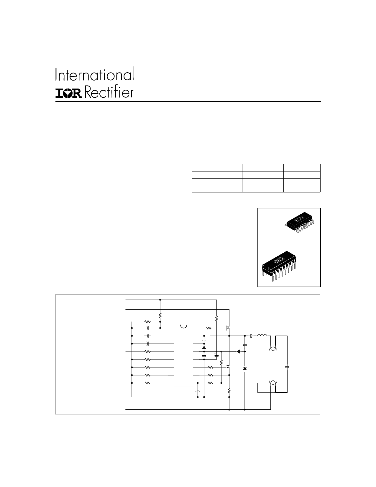
Typical Connection
+ Rectified AC Line
+ DC Bus
0.5 to 5VDC
RVDC
CVDC
CVCO
CPH
RDIM
RMAX
RMIN
RFMIN
RIPH
RVAC
1
VDC
2
VCO
3
CPH
4
DIM
5
MAX
6
MIN
7
FMIN
8
IPH
RPULL-UP
16
HO
15
VS
14
VB
13
VCC
12
COM
11
LO
10
CS
9
SD
RCS
Single Lamp Dimmable
- DC Bus
www.irf.com
1
1 page 
IR2159/IR21591 (S)
Electrical Characteristics (cont.)
VCC = VBS = VBIAS = 14V +/- 0.25V, VCS = 0.5V, VSD = 0.0V, RFMIN = 40k, CVCO = 10 nF, VDIM = 0.0V, RMAX = 33k,
RMIN = 56k, VTPH = 0.0V, CLO,HO = 1000pF, TA = 25oC unless otherwise specified.
Symbol Definition
Min. Typ. Max. Units Test Conditions
Preheat Characteristics
ICPH
CPH pin charging current
— 1.3 — µA
VCPHIGN CPH pin ignition mode threshold voltage — 5.0 —
VCPHCLMP CPH pin clamp voltage
— 10 — V
IIPH IPH pin DC source current
— 25.0 — µA IIPH = 1/RFMIN
VCSTH Peak preheat current regulation threshold
—
0.7
—
V VCSTH =(IIPH) x (RIPH)
VCPHFLT CPH pin voltage during UVLO or fault
— 0.0 — V SD = 5V, or CS = 2V,
or Tj > TSD
Ignition Characteristics
VCSTH Peak over current threshold
— 1.6 — V VCPH < 5V
Protection Characteristics
VSDTH+ Rising shutdown pin threshold voltage
— 2.0
VVDCTH+ Rising VDC pin threshold voltage
— 5.1
VSDHYS SD threshold hysteresis
— 150
VVDCHYS VDC threshold hysteresis
— 2.1
VSDCLMP SD pin clamp voltage
— 7.6
VCSTH Peak over-current latch threshold voltage — 1.6
TSD Thermal shutdown junction temperature
— 165
—
—V
— mV
—
— V ISD = 100mA
— VCPH > 5.1V
— oC
Phase Control
VCSTHZX
RFB
tBlank
Zero-crossing threshold voltage
Phase control FB resistor (Internal)
Zero-crossing internal blank time
— 0.0
— 5.7
— 400
—
—
—
V
kΩ
ns
Dimming Interface
VDIMOFF DIM pin offset voltage
— 0.5 —
VDIM
DIM pin input voltage range
0.0 — 5.0
VMINMIN DIM minimum reference voltage (MIN pin)
VMINMAX DIM maximum reference voltage (MIN pin)
—
—
1.0
3.0
—
—
V
VDIM= 5V
VDIM= 0V
VDIMTH DIM mode VCO Threshold (IR2159)
— 0.5 3.0
VDIMTH DIM mode VCO Threshold (IR21591)
— 1.1 3.0
Minimum Frequency Setting
VFMIN
FMIN pin voltage during normal operation
—
5.1
—
V
VFMINFLT FMIN pin voltage during fault mode
— 0.0 — V SD = 5V, or CS = 2V,
or Tj > TSD
www.irf.com
5
5 Page 
IR2159/IR21591 (S)
90
85
80
75
70
65
60
55 VVCO=0.5V
50
45
40
35
10 14 18 22 26 30 34 38
RFMIN KΩ
Graph 5. Frequency vs RFMIN (IR2159)
170
160
150
140
130
120
VVCO=1.1V
110
100
90
80
10 14 18 22 26 30 34 38
RFMIN KΩ
Graph 6. Frequency vs RFMIN (IR21591)
450
400
350
300
250
200
150
100
50
10 20 30 40 50 60 70
RFMIN (KΩ)
Graph 7. IMIN vs RFMIN (IR2159/IR21591)
www.irf.com
110
100
90
80
70
60
50
40
30
20
10
10 20 30 40 50 60
RFMIN (KΩ)
Graph 8. IIPH vs RFMIN (IR2159/IR21591)
70
11
11 Page | ||
| Páginas | Total 25 Páginas | |
| PDF Descargar | [ Datasheet IR2159.PDF ] | |
Hoja de datos destacado
| Número de pieza | Descripción | Fabricantes |
| IR2151 | SELF-OSCILLATING HALF-BRIDGE DRIVER | International Rectifier |
| IR2152 | SELF-OSCILLATING HALF-BRIDGE DRIVER | International Rectifier |
| IR2153 | SELF-OSCILLATING HALF-BRIDGE DRIVER | International Rectifier |
| IR21531 | SELF-OSCILLATING HALF-BRIDGE DRIVER | International Rectifier |
| Número de pieza | Descripción | Fabricantes |
| SLA6805M | High Voltage 3 phase Motor Driver IC. |
Sanken |
| SDC1742 | 12- and 14-Bit Hybrid Synchro / Resolver-to-Digital Converters. |
Analog Devices |
|
DataSheet.es es una pagina web que funciona como un repositorio de manuales o hoja de datos de muchos de los productos más populares, |
| DataSheet.es | 2020 | Privacy Policy | Contacto | Buscar |