|
|
|
PDF IRS2166DPBF Data sheet ( Hoja de datos )
| Número de pieza | IRS2166DPBF | |
| Descripción | PFC + Ballast Control IC | |
| Fabricantes | International Rectifier | |
| Logotipo | ||
Hay una vista previa y un enlace de descarga de IRS2166DPBF (archivo pdf) en la parte inferior de esta página. Total 17 Páginas | ||
|
No Preview Available !
www.DataSheet4U.com
Data Sheet No. PD60292
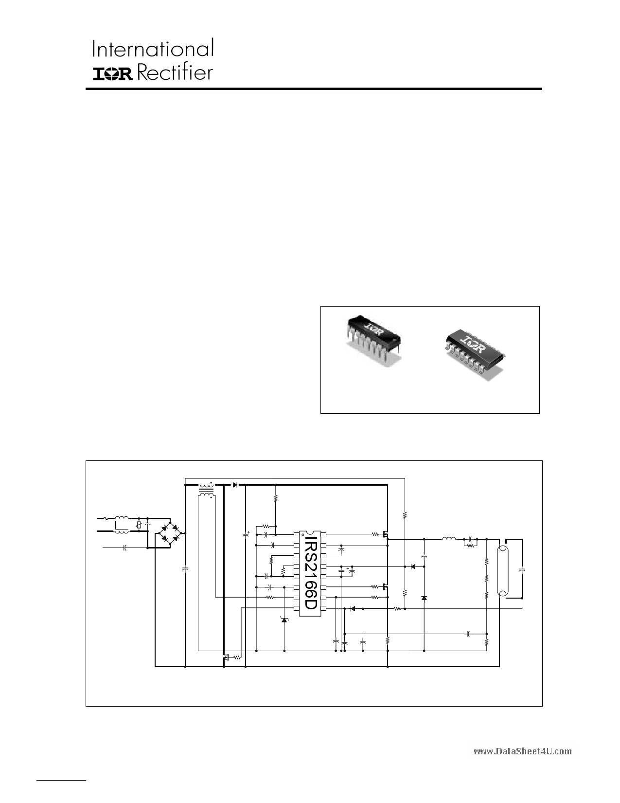
IRS2166D(S)PbF
PFC + BALLAST CONTROL IC
Features
PFC, ballast control and 600 V half-bridge driver in one IC
Critical-conduction mode boost-type PFC
Programmable half-bridge over-current protection
Programmable preheat frequency
Programmable deadtime
Programmable preheat time
Programmable run frequency
End-of-life window comparator pin
Internal up/down current-sense fault counter
DC bus undervoltage reset
Lamp removal/auto-restart shutdown pin
Internal bootstrap MOSFET
Internal 15.6 V zener clamp diode on VCC
Micropower startup (250 µA)
Latch immunity and ESD protection
Description
The IRS2166D is a fully integrated, fully protected 600 V
ballast control IC designed to drive all types of fluorescent
lamps. The IRS2166D is based on the popular IR2166
control IC with additional improvements to increase ballast
performance. PFC circuitry operates in critical conduction
mode and provides high PF, low THD, and DC bus
regulation. The IRS2166D features include programmable
preheat and run frequencies, programmable preheat time,
and programmable end-of-life protection. Comprehensive
protection features such as protection from failure of a lamp
to strike, filament failures, end-of-life protection, DC bus
undervoltage reset as well as an automatic restart function,
have been included in the design.
System Features
Improved VBUS regulation voltage tolerance
Increased SD pin shutdown voltage threshold hysteresis
Changed EOL pin internal 2.0 V bias to a +/-10 µA OTA
Internal bootstrap MOSFET
Packages
16-Lead PDIP
IRS2166DPbF
16-Lead SOIC
IRS2166DSPbF
Application Diagram (Typical Only)
LPFC
DPFC
RBUS
F1
L
N
GND
RV1
L1 C1
BR1
CY
C2
CBUS
MPFC
RPFC
RVDC
CVDC
CPH
VBUS 1
CPH 2
RT
CT
RT 3
RPH 4
RPH
CT 5
CCOMP COMP6
RZX ZX 7
PFC 8
16 HO
15 VS
14 VB
13VCCVCCC1
12COM
11 LO
10 CS
SD/EOL
9
CBOOT
RH
O
CVCC2
RL
O
DSD
RLIM
DCOMP
IC BALLAST
CCS
CSD1
CSD2
RSUPPLY
MHS
LRES
DCP2
CSNUB
ML
S
RPU
RSD
DCP1
RCS
CDC
RDC
REOL1
REOL2
REOL3
CEOL
REOL4
Note: Thick traces represent high-frequency, high-current paths.
Lead lengths should be minimized and power and IC grounds should be separated to avoid high-frequency
noise problems.
CRES
www.irf.com
Page 1
1 page 
www.DataSheet4U.com
IRS2166D(S)PbF
Schematic Block Diagram
VCC
13
COM
15.6 V 12
S1
RT 3
R
S2
40 K
R
CT 5
RDT
3.0K
VTH
R
S3
3 uA
S4
RPH 4
R
S5
R
CPH 2
VCC
S6
RUN
Soft
Start
Driver
Logic
TQ
RQ
Fault
Counter
Fault
Logic
SQ
R1
R2 Q
VCC
Bootstrap
Control
High-
Side
Driver
14 VB
16 HO
15 VS
Low-
Side
Driver
11 LO
3.0 V2 V
10 CS
1.25 V
Ballast Control
PFC Control
3.0 V
SQ
RQ
VCC
UVLO
QS
R1
Q R2
1.0 V
9 SD/EOL
5V
VBUS 1
COMP 6
4.0 V
Gain
4.3 V
OVP
3.5 V
4.0 V
RS1
SQ
RQ
ZX 7
6.7 V
1.0 V
RS2
SQ
R1
R2 Q
RS3
SQ
RQ
SQ
R1 RS4
R2 Q
3V
VCC
8 PFC
400 us
Watch Dog
Timer
Please Note: All values shown in block diagram are typical values only
www.irf.com
Page 5
5 Page 
www.DataSheet4U.com
IRS2166D(S)PbF
VCC is above VCCUV+ (ballast power on) and SD is pulled
above 5.0 V (VSDTH+) and back below 3.0 V (VSDTH-) (lamp
re-insertion), the IC will enter preheat mode and begin
oscillating again.
LO
50 Pulses
The current sense function will force the IC to enter fault
mode only after the voltage at the CS pin has been
greater than 1.20 V (VCSTH+) for 100 (nEVENTS) consecutive
cycles of LO. The over-current function at the CS pin
(see Fig. 5) will only consecutive cycles of LO. The over-
current function at the CS pin (see Fig. 5) will only work
with over-current events that occur during the LO on-time.
If the over-current faults are not consecutive, then the
internal fault counter will count back down each cycle
when there is no fault present. Should an over-current
fault occur only for a few cycles and then not occur again,
the counter will eventually count back down to zero. The
over-current fault counter is enabled during preheat and
ignition modes and disabled during run mode. During run
mode, the IC will enter fault mode after a single over-
current event at the CS pin.
II. PFC Section
Functional Description
In most electronic ballasts it is necessary to have the
circuit act as a pure resistive load to the AC input line
voltage. The degree to which the circuit matches a pure
resistor is measured by the phase shift between the input
voltage and input current and how well the shape of the
input current waveform matches the shape of the
sinusoidal input voltage. The cosine of the phase angle
between the input voltage and input current is defined as
the power factor (PF), and how well the shape of the input
current waveform matches the shape of the input voltage
is determined by the total harmonic distortion (THD). A
power factor of 1.0 (maximum) corresponds to zero
phase shift and a THD of 0% represents a pure sinewave
(no distortion). For this reason it is desirable to have a
high PF and a low THD. To achieve this, the IRS2166D
includes an active power factor correction (PFC) circuit
which, for an AC line input voltage, produces an AC line
input current.
CS
2.0V
Preheat or Ignition Mode
Fault Mode
Fig. 5: CS & LO Waveforms
When the switch MPFC is turned on, the inductor LPFC is
connected between the rectified line input (+) and (-)
causing the current in LPFC to charge up linearly. When
MPFC is turned off, LPFC is connected between the rectified
line input (+) and the DC bus capacitor CBUS (through
diode DPFC) and the stored current in LPFC flows into CBUS.
As MPFC is turned on and off at a high-frequency, the
voltage on CBUS charges up to a specified voltage. The
feedback loop of the IRS2166D regulates this voltage to a
fixed value by continuously monitoring the DC voltage
and adjusting the on-time of MPFC accordingly. For an
increasing DC bus the on-time is decreased, and for a
decreasing DC bus the on-time is increased. This
negative feedback control is performed with a slow loop
speed and a low loop gain such that the average inductor
current smoothly follows the low-frequency line input
voltage for high power factor and low THD. The on-time
of MPFC therefore appears to be fixed (with an additional
modulation to be discussed later) over several cycles of
the line voltage. With a fixed on-time, and an off-time
determined by the inductor current discharging to zero,
the result is a system where the switching frequency is
free-running and constantly changing from a high
frequency near the zero crossing of the AC input line
voltage, to a lower frequency at the peaks (Fig. 7).
V, I
The control method implemented in the IRS2166D is for a
boost-type converter (Fig. 6) running in critical-conduction
mode (CCM). This means that during each switching
cycle of the PFC MOSFET, the circuit waits until the
inductor current discharges to zero before turning the
PFC MOSFET on again. The PFC MOSFET is turned on
and off at a much higher frequency (>10 kHz) than the
line input frequency (50 Hz to 60 Hz).
LPFC
(+)
DPFC
DC Bus
MPFC
+
CBUS
(-)
Fig. 6: Boost-type PFC circuit
t
Fig. 7: Sinusoidal line input voltage (solid line), triangular
PFC inductor current and smoothed sinusoidal line input
current (dashed line) over one half-cycle of the line input
voltage
When the line input voltage is low (near the zero
crossing), the inductor current will charge up to a small
amount and the discharge time will be fast resulting in a
high switching frequency. When the input line voltage is
high (near the peak), the inductor current will charge up to
a higher amount and the discharge time will be longer
giving a lower switching frequency. The triangular PFC
inductor current is then smoothed by the EMI filter to
produce a sinusoidal line input current.
www.irf.com
Page 11
11 Page | ||
| Páginas | Total 17 Páginas | |
| PDF Descargar | [ Datasheet IRS2166DPBF.PDF ] | |
Hoja de datos destacado
| Número de pieza | Descripción | Fabricantes |
| IRS2166DPBF | PFC + Ballast Control IC | International Rectifier |
| Número de pieza | Descripción | Fabricantes |
| SLA6805M | High Voltage 3 phase Motor Driver IC. |
Sanken |
| SDC1742 | 12- and 14-Bit Hybrid Synchro / Resolver-to-Digital Converters. |
Analog Devices |
|
DataSheet.es es una pagina web que funciona como un repositorio de manuales o hoja de datos de muchos de los productos más populares, |
| DataSheet.es | 2020 | Privacy Policy | Contacto | Buscar |