|
|
|
PDF 74FST3125 Data sheet ( Hoja de datos )
| Número de pieza | 74FST3125 | |
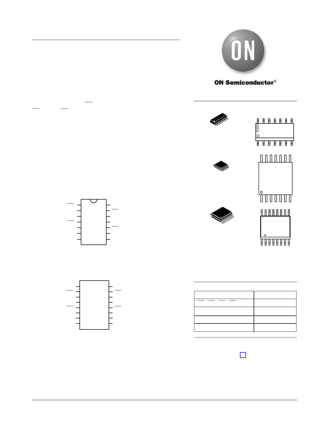
| Descripción | 4-Bit Bus Switch | |
| Fabricantes | ON Semiconductor | |
| Logotipo | ||
Hay una vista previa y un enlace de descarga de 74FST3125 (archivo pdf) en la parte inferior de esta página. Total 8 Páginas | ||
|
No Preview Available !
www.DataSheet4U.com
74FST3125
4−Bit Bus Switch
The ON Semiconductor 74FST3125 is a quad, high performance
switch. The device is CMOS TTL compatible when operating between
4 and 5.5 Volts. The device exhibits extremely low RON and adds
nearly zero propagation delay. The device adds no noise or ground
bounce to the system.
The device consists of four independent 1−bit switches with
separate Output/Enable (OE) pins. Port A is connected to Port B when
OE is low. If OE is high, the switch is high Z.
Features
• RON t 4 W Typical
• Less Than 0.25 ns−Max Delay Through Switch
• Nearly Zero Standby Current
• No Circuit Bounce
• Control Inputs are TTL/CMOS Compatible
• Pin−For−Pin Compatible With QS3125, FST3125, CBT3125
• All Popular Packages: QSOP−16, TSSOP−14, SOIC−14
• All Devices in Package TSSOP are Inherently Pb−Free*
OE1
1A
1B
OE2
2A
2B
GND
1
2
3
4
5
6
7
14 VCC
13 OE4
12 4A
11 4B
10 OE3
9 3A
8 3B
Figure 1. Pin Assignment for
SOIC and TSSOP
NC
OE1
1A
1B
OE2
2A
2B
GND
1
2
3
4
5
6
7
8
16 VCC
15 OE4
14 4A
13 4B
12 OE3
11 3A
10 3B
9 NC
Figure 2. Pin Assignment
for QSOP
http://onsemi.com
14
1
SOIC−14
D SUFFIX
CASE 751A
MARKING
DIAGRAMS
14
FST3125
AWLYWW
1
14
14
1
TSSOP−14
DT SUFFIX
CASE 948G
FST
3125
ALYW
1
16
1
QSOP−16
QS SUFFIX
CASE 492
16
S3125
ALYW
1
A = Assembly Location
L, WL = Wafer Lot
Y = Year
W, WW = Work Week
PIN NAMES
Pin
OE1, OE2, OE3, OE4
1A, 2A, 3A, 4A
1B, 2B, 3B, 4B
NC
Description
Bus Switch Enables
Bus A
Bus B
Not Connected
ORDERING INFORMATION
See detailed ordering and shipping information in the package
dimensions section on page 2 of this data sheet.
*For additional information on our Pb−Free strategy and soldering details, please
download the ON Semiconductor Soldering and Mounting Techniques
Reference Manual, SOLDERRM/D.
© Semiconductor Components Industries, LLC, 2005
January, 2005 − Rev. 2
1
Publication Order Number:
74FST3125/D
1 page 
74FST3125
AC Loading and Waveforms
FROM
OUTPUT
UNDER
TEST
VI
500 W
500 W
CL*
NOTES:
1. Input driven by 50 W source terminated in 50 W.
2. CL includes load and stray capacitance.
*CL = 50 pF
Figure 4. AC Test Circuit
SWITCH
INPUT
10 %
tPLH
tf = 2.5 nS
90 %
1.5 V
90 %
1.5 V
OUTPUT
1.5 V
tf = 2.5 nS
3.0 V
Vmi
10 %
GND
tPLH
VOH
1.5 V
VOL
Figure 5. Propagation Delays
ENABLE
INPUT
tf = 2.5 nS
90 %
1.5 V
tPZL
OUTPUT
tPZH
OUTPUT
10 % 10 %
1.5 V
1.5 V
tf = 2.5 nS
90 % 3.0 V
1.5 V
GND
tPZL
VOL + 0.3 V
VOL
tPHZL
VOH
VOH − 0.3 V
Figure 6. Enable/Disable Delays
http://onsemi.com
5
5 Page | ||
| Páginas | Total 8 Páginas | |
| PDF Descargar | [ Datasheet 74FST3125.PDF ] | |
Hoja de datos destacado
| Número de pieza | Descripción | Fabricantes |
| 74FST3125 | 4-Bit Bus Switch | ON Semiconductor |
| 74FST3126 | 4-Bit Bus Switch | ON |
| 74FST3126D | 4-Bit Bus Switch | ON |
| 74FST3126DR2 | 4-Bit Bus Switch | ON |
| Número de pieza | Descripción | Fabricantes |
| SLA6805M | High Voltage 3 phase Motor Driver IC. |
Sanken |
| SDC1742 | 12- and 14-Bit Hybrid Synchro / Resolver-to-Digital Converters. |
Analog Devices |
|
DataSheet.es es una pagina web que funciona como un repositorio de manuales o hoja de datos de muchos de los productos más populares, |
| DataSheet.es | 2020 | Privacy Policy | Contacto | Buscar |