|
|
|
PDF NJW1143 Data sheet ( Hoja de datos )
| Número de pieza | NJW1143 | |
| Descripción | AUDIO PROCESSOR | |
| Fabricantes | New Japan Radio | |
| Logotipo | ||
Hay una vista previa y un enlace de descarga de NJW1143 (archivo pdf) en la parte inferior de esta página. Total 17 Páginas | ||
|
No Preview Available !
www.DataSheet4U.com
NJW1143
AUDIO PROCESSOR
s GENERAL DESCRIPTION
The NJW1143 is an audio processor which includes volume,
balance, tone control, surround, simulated stereo and AGC
function.
Also the NJW1143 features high precision characteristics about
channel balance, it is less than ±1.0dB at –70dB attenuation.
All of internal status and variables are controlled by I2C BUS.
Selectable 4-slave address is applicable to multi-speaker system.
It is suitable for any TV set.
s PACKAGE OUTLINE
NJW1143M
s FEATURES
q Operating Voltage
8 to 13V
q I2C BUS Interface
(Fast mode applicable, Selectable 4-Slave address, 3V I/F applicable)
q Low Output Noise
q AGC Circuit (Selectable 4-stage compression level via I2C BUS)
q "eala" (NJRC Surround)
q Simulated Surround
q Bi-CMOS Technology
q Package Outline
DMP24
DataSheet4U.com
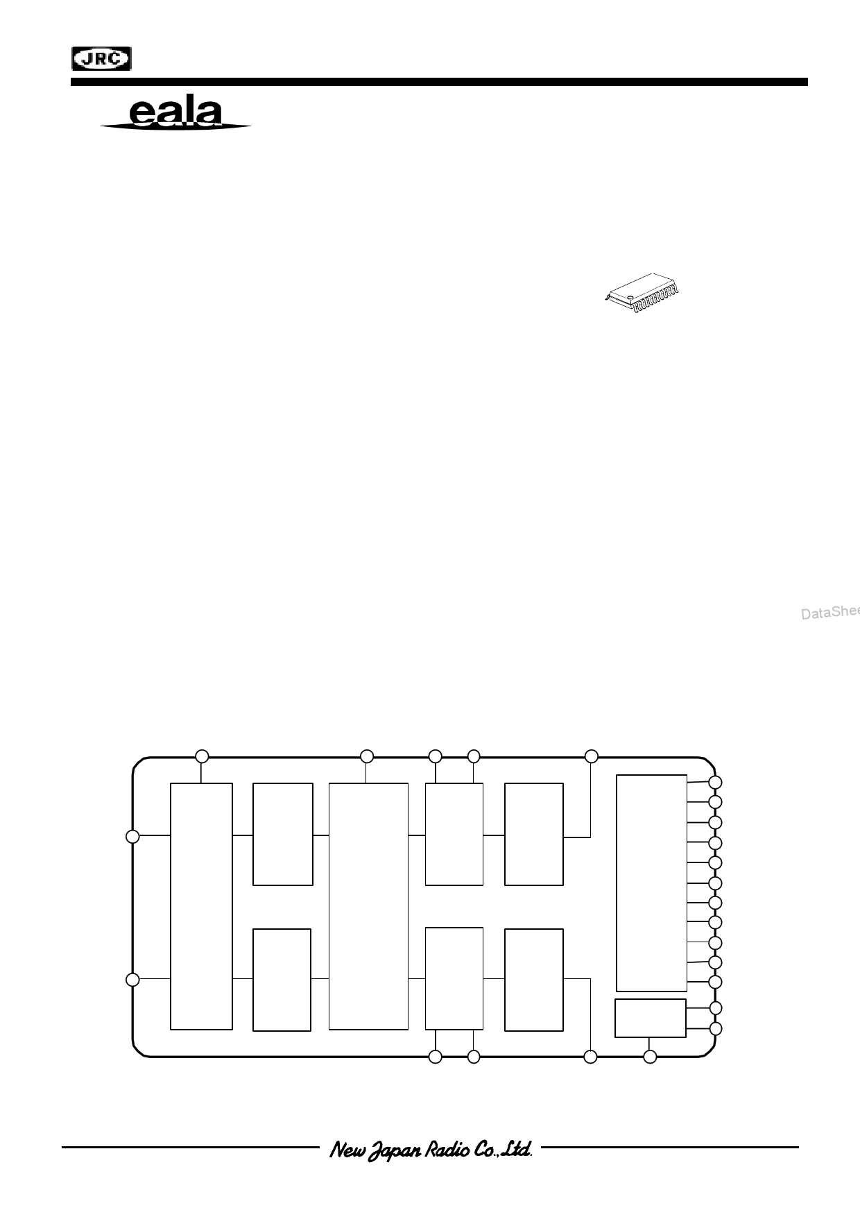
s BLOCK DIAGRAM
DataShee
INa
INb
DataSheet4U.com
AGC
SRFIL
TONE TONE
-Ha -La
OUTa
AGC
VOL1
e ala
&
Sim ulate
Stere o
TONE
VOL2
I2C Bus
Interface
VOL1
TONE
VOL2
Bias
TONE TONE
-Hb -Lb
OUTb Vref
CVO
CBA
CTH
CTL
CSR
AUX0
AUX1
ADR0
ADR1
SCL
SDA
V+
GND
-1-
1 page 
www.DataSheet4U.com
NJW1143
et4U.com
s I2C BUS CHARACTERISTICS (SDA, SCL)
I2C BUS Load Conditions: Pull up resistance 4kΩ (Connected to +5V), Load capacitance 200pF (Connected to GND)
PARAMETER
Standard mode
Fast mode
SYMBOL
UNIT
MIN. TYP. MAX. MIN. TYP. MAX.
Low Level Input Voltage
VIL 0.0
High Level Input Voltage
VIH 2.7
Hysteresis of Schmitt trigger inputs
Vhys
-
Low level output voltage (3mA at SDA pin)
Output fall time from VIHmin to VILmax with
a bus capacitance from 10pF to 400pF
Pulse width of spikes which must be suppressed
by the input filter
Input current each I/O pin with an input voltage
between 0.1VDD and 0.9VDDmax
Capacitance for each I/O pin
VOL
tof
tSP
Ii
Ci
0
-
-
-10
-
SCL clock frequency
fSCL
-
Hold time (repeated) START condition.
tHD:STA
4.0
Low period of the SCL clock
tLOW
4.7
High period of the SCL clock
tHIGH
4.0
Set-up time for a repeated START condition
tSU:STA
4.7
Data hold time
tHD:DAT
0
Data set-up time
Rise time of both SDA and SCL signals
DataStShUe:DeAtT4U.co2m50
tr -
Fall time of both SDA and SCL signals
tf -
Set-up time for STOP condition
tSU:STO
4.0
Bus free time between a STOP and START condition tBUF 4.7
Capacitive load for each bus line
Cb -
Noise margin at the Low level
VnL 0.5
Noise margin at the High level
VnH 1
- 1.5 0.0 - 1.5
V
- 5.0 2.7 - 5.0
V
- - 0.25 - -
V
- 0.4 0
- 0.4
V
-
250
20
+0.1Cb
-
250
ns
- - 0 - 50 ns
-
10 -10
-
10
µA
- 10 -
- 10 pF
- 100 -
- 400 kHz
- - 0.6 - - µs
- - 1.3 - - µs
- - 0.6 - - µs
- - 0.6 - - µs
- 3.45 0
- 0.9 µs
- - 100 - - ns
- 1000 -
- 300 ns DataShee
- 300 -
- 300 ns
- - 0.6 - - µs
- - 1.3 - - µs
- 400 -
- 400 pF
- - 0.5 - -
V
- -1- -
V
Cb ; total capacitance of one bus line in pF.
SDA
tf tr
SCL
tHD:STA
S
tLOW
DataSheet4U.com
tSU:DAT
tf
tHD:STA
tHD:DAT
tHIGH
tSU:STA
Sr
tSP tr
tBUF
tSU:STO
P
S
-5-
5 Page 
www.DataSheet4U.com
NJW1143
s I2C CONTROL COMMAND DESCRIPTION
qMASTER VOLUME CONTROL
Select
BIT
Address
D7
D6
D5
D4
D3
D2
D1
D0
00H VOL
The volume controls both Ach and Bch by the 0.5dB step.
The volume is consisted of volume1 and volume2. The level is divided into half to each volume1 and
volume2.
qBALANCE, AGC AND INPUT SELECTOR SETTINGS
Select
BIT
Address
D7
D6
D5
D4
D3
D2
D1
D0
01H CHS
BAL
SUR
et4U.com
•CHS: Channel select for balance control
“0”: Ach “Bch is attenuated”
“1”: Bch “Ach is attenuated”
•BAL: Balance control for both Ach and Bch (1dB/Step)
The balance is consisted of volume2 alone. Volume1 does not operate on balance.
•SUR : Surround Setting
Surround Setting
SUR
D1 D0
Remarks
Surround OFF
0 0 Input through
Simulated Stereo mode
0 1 For monaural signal input only
"eala" High mode
1 DataShee0t4U.coSmurround Effect Small ( 8.0dB typ. )
"eala" Low mode
1 1 Surround Effect Large (12.0dB typ. )
DataShee
qTONE CONTROL (Bass) and AGC SETTINGS
Select
BIT
Address
D7
D6
D5
D4
D3
02H BCB
BASS
D2
AGC-SW
D1 D0
AGC-FLAT
•BCB : Bass Boost or Cut
“0” : Cut
“1” : Boost
•BASS : BASS Level
Cut Level : -15 to 0dB(1dB/Step)
Boost Level : 0 to +15dB(1dB/Step)
•AGC-SW : AGC ON/OFF Switch
“0” : AGC OFF
“1” : AGC ON (Default : 100mVrms)
•AGC-FLAT : AGC Flat Level
AGC Flat Level
AGC-FLAT
D1 D0
100mVrms
00
200mVrms
01
300mVrms
10
400mVrms
11
DataSheet4U.com
- 11 -
11 Page | ||
| Páginas | Total 17 Páginas | |
| PDF Descargar | [ Datasheet NJW1143.PDF ] | |
Hoja de datos destacado
| Número de pieza | Descripción | Fabricantes |
| NJW1140 | AUDIO PROCESSOR with SRS | New Japan Radio |
| NJW1141 | AUDIO PROCESSOR | New Japan Radio |
| NJW1142 | AUDIO PROCESSOR | New Japan Radio |
| NJW1142A | Audio Processor | JRC |
| Número de pieza | Descripción | Fabricantes |
| SLA6805M | High Voltage 3 phase Motor Driver IC. |
Sanken |
| SDC1742 | 12- and 14-Bit Hybrid Synchro / Resolver-to-Digital Converters. |
Analog Devices |
|
DataSheet.es es una pagina web que funciona como un repositorio de manuales o hoja de datos de muchos de los productos más populares, |
| DataSheet.es | 2020 | Privacy Policy | Contacto | Buscar |