|
|
|
PDF LTC3721-1 Data sheet ( Hoja de datos )
| Número de pieza | LTC3721-1 | |
| Descripción | Push-Pull PWM Controller | |
| Fabricantes | Linear Integrated Systems | |
| Logotipo | ||
Hay una vista previa y un enlace de descarga de LTC3721-1 (archivo pdf) en la parte inferior de esta página. Total 16 Páginas | ||
|
No Preview Available !
www.DataSheet4U.com
LTC3721-1
Push-Pull PWM Controller
FEATURES
DESCRIPTIO
■ High Efficiency Push-Pull PWM
The LTC®3721-1 push-pull PWM controller provides all of
■ 1.5A Sink, 1A Source Output Drivers
the control and protection functions necessary for com-
■ Adjustable Push-Pull Dead-Time
pact and highly efficient, isolated power converters. High
■ Adjustable System Undervoltage Lockout and
integration minimizes external component count, while
Hysteresis
preserving design flexibility.
■ Adjustable Leading Edge Blanking
■ Low Start-Up and Quiescent Currents
■ Current Mode Operation
■ Single Resistor Slope Compensation
■ VCC UVLO and 25mA Shunt Regulator
■ Programmable Fixed Frequency Operation to 1MHz
■ Soft-Start, Cycle-by-Cycle Current Limiting and
Hiccup Mode Short-Circuit Protection
■ 5V, 15mA Low Dropout Regulator
■ 16-Pin SSOP and (4mm × 4mm) QFN Packages
U
APPLICATIO S
The robust push-pull output stages switch at half the
oscillator frequency. Dead-time is independently pro-
grammed with an external resistor. A UVLO program input
provides precise system turn-on and turn off voltages. The
LTC3721-1 features peak current mode control with pro-
grammable slope compensation and leading edge
blanking.
The LTC3721-1 features extremely low operating and
start-up currents and reliable short-circuit and
overtemperature protection. The LTC3721-1 is offered in
16-pin SSOP and (4mm × 4mm) QFN packages.
DataShee
, LTC and LT are registered trademarks of Linear Technology Corporation.
■ Telecommunications, Infrastructure Power SysDteamtasSheet4U.com
■ Distributed Power Architectures
■ Server Power Supplies
■ High Density Power Modules
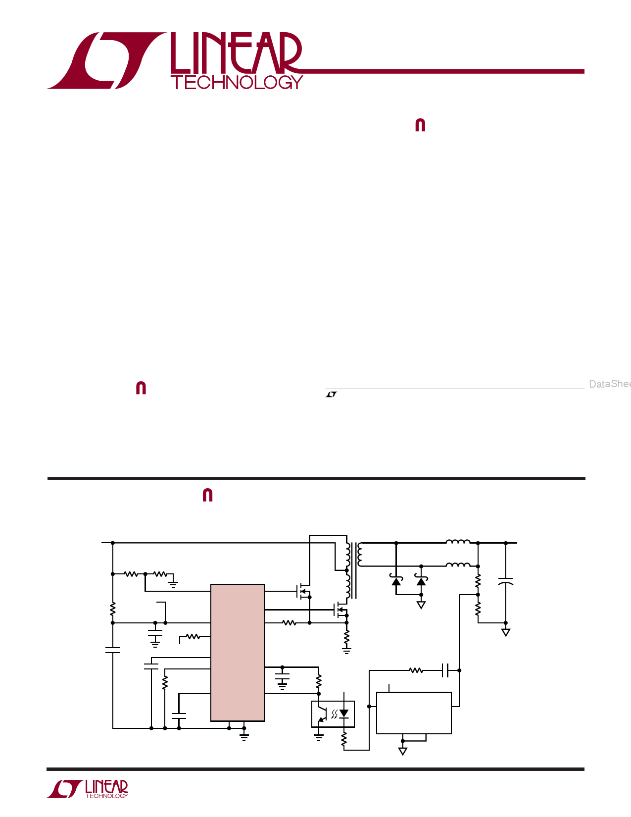
TYPICAL APPLICATIO
VIN
Isolated Push-Pull Converter
DataSheet4U.com
FROM
AUXILIARY
WINDING
VREF
UVLO
DRVA
DRVB
VCC CS
DPRG
LTC3721-1
CT
RLEB
VREF
SS COMP
FB GND
RCS
VOUT
VOUT
V+
COLL
COMP
LT1431
RTOP
RREF
RMID
GND-F GND-S
VOUT
+
37211 TA01
sn37211 37211fs
1
1 page 
www.DataSheet4U.com
LTC3721-1
TYPICAL PERFOR A CE CHARACTERISTICS (TA = 25°C unless otherwise noted)
Error Amplifier Gain/Phase
100
80
60
40
20
0
–180
–270
–360
10 100 1k 10k 100k 1M 10M
FREQUENCY (Hz)
372311 G07
et4U.com
Slope Current vs Temperature
90
80
70 CT = 2.25V
60
50
40
30 CT = 1V
20
10
0
–55
–25 5 35 65
TEMPERATURE (°C)
95 125
372311 G10
Start-Up ICC vs Temperature
190
180
170
160
150
140
130
120
110
100
–55
–25 5 35 65
TEMPERATURE (°C)
95 125
372311 G08
VCC Shunt Voltage vs
Temperature
10.5
ICC = 10mA
10.4
10.3 DataSheet4U.com
10.2
10.1
10.0
9.9
9.8
–55
–25 5 35 65
TEMPERATURE (°C)
95 125
372311 G11
Deadtime vs RDPRG
275
250
225
200k PREBIAS
200
175
150
NO 200k PREBIAS
125
100
75
50
0 50 100 150 200 250 300 350 400 450 500
RDPRG (kΩ)
372311 G09
FB Input Voltage vs Temperature
1.205
1.204
DataShee
1.203
1.202
1.201
1.200
1.199
1.198
1.197
–55
–25 5 35 65
TEMPERATURE (°C)
95 125
372311 G12
DataSheet4U.com
sn37211 37211fs
5
5 Page 
www.DataSheet4U.com
U
OPERATIO
LTC3721-1
that the positive voltage square wave is produced while the Current Sensing and Overcurrent Protection
output inductor is freewheeling. An advantage of this
technique over the previous is that it does not require a
separate filter inductor and since the voltage is derived
from the well-regulated output voltage, it is also well
controlled. One disadvantage is that this winding will
require the same safety isolation that is required for the
main transformer. Another disadvantage is that a much
Current sensing provides feedback for the current mode
control loop and protection from overload conditions. The
LTC3721-1 is compatible with either resistive sensing or
current transformer methods. Internally connected to CS
are two comparators that provide pulse-by-pulse and
overcurrent shutdown functions respectively, (Figure 6).
larger VCC filter capacitor is needed, since it does not The pulse-by-pulse comparator has a 300mV nominal
generate a voltage as the output is first starting up, or threshold. If the 300mV threshold is exceeded, the PWM
during short-circuit conditions.
cycle is terminated. The overcurrent comparator is set
approximately 2x higher than the pulse-by-pulse level. If
Programming the LTC3721-1 Oscillator
the current signal exceeds this level, the PWM cycle is
The high accuracy LTC3721-1 oscillator circuit provides terminated, the soft-start capacitor is quickly discharged
flexibility to program the switching frequency and slope and a soft-start cycle is initiated. If the overcurrent condi-
compensation required for current mode control. The
oscillator circuit produces a 2.35V peak-to-peak ampli-
tude ramp waveform on CT. Typical maximum duty cycles
et4U.com of 49% are possible. The oscillator is capable of operation
up to 1MHz by the following equation:
tion persists, the LTC3721-1 halts PWM operation and
waits for the soft-start capacitor to charge up to approxi-
mately 4V before a retry is allowed. The soft-start capaci-
tor is charged by an internal 13µA current source. If the
fault condition has not cleared when soft-start reaches 4V,
DataShee
DataSheet4thUe.csoomft-start pin is again discharged and a new cycle is
CT = 1/(14.8k • FOSC)
initiated. This is referred to as hiccup mode operation. In
Note that this is the frequency seen on CT. The output
drivers switch at 1/2 of this frequency. Also note that
higher switching frequency and added driver dead-time
via DPRG will reduce the maximum duty cycle.
The LTC3721-1 derives a compensating slope current
from the oscillator ramp waveform and sources this
current out of CS. The desired level of slope compensation
normal operation and under most abnormal conditions,
the pulse-by-pulse comparator is fast enough to prevent
hiccup mode operation. In severe cases, however, with
high input voltage, very low RDS(ON) MOSFETs and a
shorted output, or with saturating magnetics, the
overcurrent comparator provides a means of protecting
the power converter.
is selected with an external resistor connected between CS
and the external current sense resistor, (Figure 5).
LTC3721-1
CT
I = V(CT)
33k
CS RSLOPE
SWITCH
CURRENT
PULSE BY PULSE
CURRENT LIMIT
+ PWM
CS 300mV –
OVERLOAD
RCS CURRENT LIMIT
+
650mV –
UVLO
ENABLE
PWM
LATCH
Q
UVLO
PWM ENABLE
LOGIC
S
SQ
R
H = SHUTDOWN
OUTPUTS
SQ Q
R
4.1V
0.4V
13µA
SS
CSS
ADDED
33k SLOPE
RCS
Q
CURRENT SENSE
WAVEFORM
37211 F05
37211 F06
Figure 5. Slope Compensation Circuitry
Figure 6. Current Sense/Fault Circuitry Detail
DataSheet4U.com
sn37211 37211fs
11
11 Page | ||
| Páginas | Total 16 Páginas | |
| PDF Descargar | [ Datasheet LTC3721-1.PDF ] | |
Hoja de datos destacado
| Número de pieza | Descripción | Fabricantes |
| LTC3721-1 | Push-Pull PWM Controller | Linear Integrated Systems |
| LTC3721-1 | Push-Pull PWM Controller | Linear |
| Número de pieza | Descripción | Fabricantes |
| SLA6805M | High Voltage 3 phase Motor Driver IC. |
Sanken |
| SDC1742 | 12- and 14-Bit Hybrid Synchro / Resolver-to-Digital Converters. |
Analog Devices |
|
DataSheet.es es una pagina web que funciona como un repositorio de manuales o hoja de datos de muchos de los productos más populares, |
| DataSheet.es | 2020 | Privacy Policy | Contacto | Buscar |