|
|
|
PDF 06035C471JA72A Data sheet ( Hoja de datos )
| Número de pieza | 06035C471JA72A | |
| Descripción | X7R Dielectric | |
| Fabricantes | AVX Corporation | |
| Logotipo | ||
Hay una vista previa y un enlace de descarga de 06035C471JA72A (archivo pdf) en la parte inferior de esta página. Total 18 Páginas | ||
|
No Preview Available !
www.DataSheet4U.com
X7R Dielectric
General Specifications
X7R formulations are called “temperature stable” ceramics
and fall into EIA Class II materials. X7R is the most popular
of these intermediate dielectric constant materials. Its tem-
perature variation of capacitance is within ±15% from
-55°C to +125°C. This capacitance change is non-linear.
Capacitance for X7R varies under the influence of electrical
operating conditions such as voltage and frequency.
X7R dielectric chip usage covers the broad spectrum of
industrial applications where known changes in capaci-
tance due to applied voltages are acceptable.
PART NUMBER (see page 2 for complete part number explanation)
0805
5
C 103 M
A
T
2
A
Size
(L" x W")
Voltage
4V = 4
6.3V = 6
10V = Z
16V = Y
25V = 3
50V = 5
100V = 1
200V = 2
500V = 7
Dielectric
X7R = C
Capacitance Capacitance
Failure
Code (In pF) Tolerance
Rate
2 Sig. Digits + J = ± 5%
A = Not
Number of
K = ±10%
Applicable
Zeros DataSMh=e±e2t40%U.com
Terminations
T = Plated Ni
and Sn
7 = Gold
Plated
Packaging
2 = 7" Reel
4 = 13" Reel
7 = Bulk Cass.
9 = Bulk
Contact
Factory For
Multiples
Special
Code
A = Std.
Product
DataShee
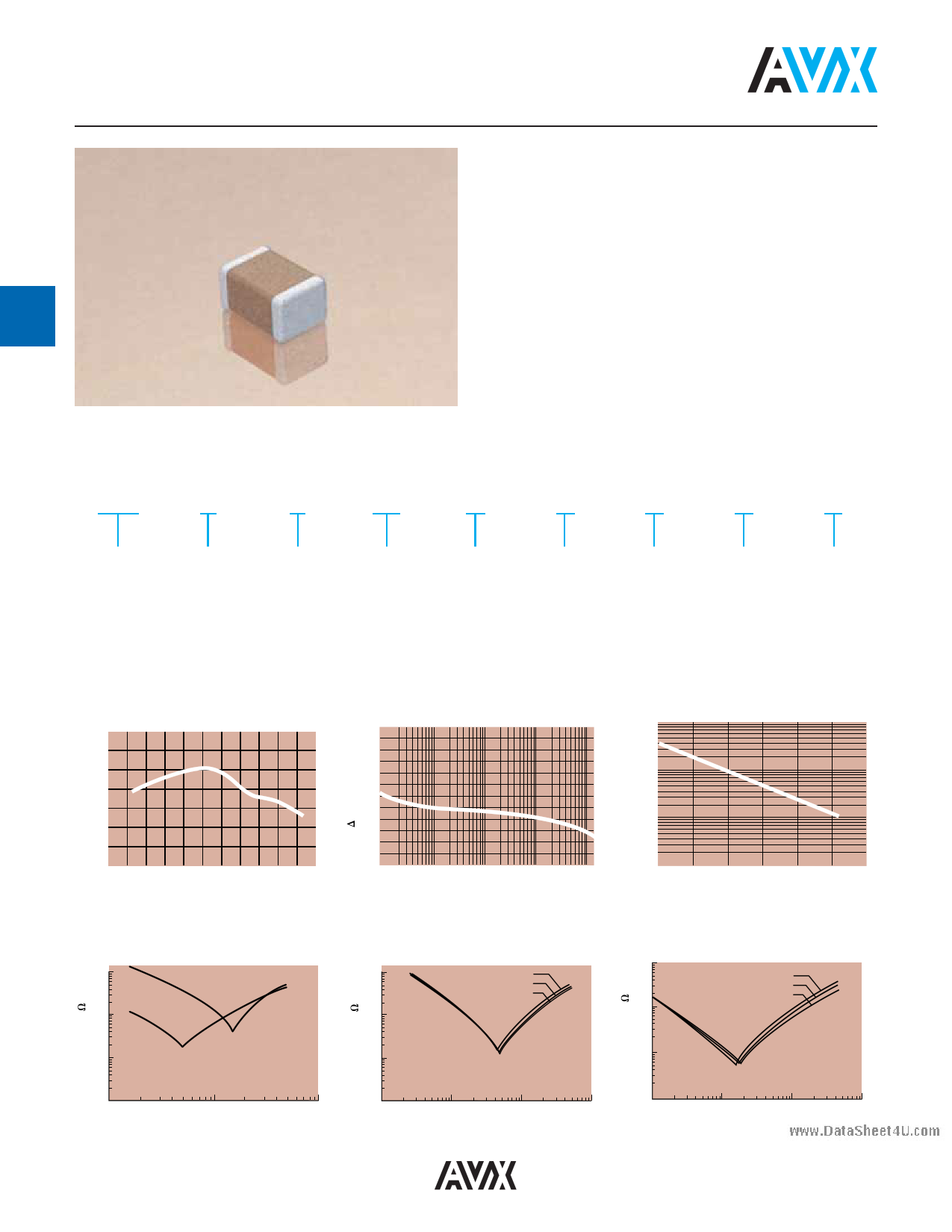
X7R Dielectric
Typical Temperature Coefficient
10
5
0
-5
-10
-15
-20
-25
-60 -40 -20 0 20 40 60 80 100 120 140
Temperature °C
Variation of Impedance with Cap Value
Impedance vs. Frequency
1,000 pF vs. 10,000 pF - X7R
0805
10.00
1,000 pF
10,000 pF
1.00
⌬ Capacitance vs. Frequency
+30
+20
+10
0
-10
-20
-30
1KHz
10 KHz
100 KHz
Frequency
1 MHz
10 MHz
Insulation Resistance vs Temperature
10,000
1,000
100
0
0 20 40 60 80 100 120
Temperature °C
Variation of Impedance with Chip Size
Impedance vs. Frequency
10,000 pF - X7R
10 1206
0805
1210
1.0
Variation of Impedance with Chip Size
Impedance vs. Frequency
100,000 pF - X7R
10
1206
0805
1210
1.0
0.10 0.1 0.1
0.01
10
DataSheet4U.com
12
100
Frequency, MHz
1000
.01
1
10 100
Frequency, MHz
1,000
.01
1
10 100
Frequency, MHz
1,000
DataSheet4 U .com
1 page 
www.DataSheet4U.com
Packaging of Chip Components
Automatic Insertion Packaging
TAPE & REEL QUANTITIES
All tape and reel specifications are in compliance with RS481.
Paper or Embossed Carrier
Embossed Only
Paper Only
Qty. per Reel/7" Reel
Qty. per Reel/13" Reel
8mm
0612, 0508, 0805, 1206,
1210
0201, 0306, 0402, 0603
2,000, 3,000 or 4,000, 10,000, 15,000
Contact factory for exact quantity
5,000, 10,000, 50,000
Contact factory for exact quantity
12mm
1808
3,000
10,000
1812, 1825
2220, 2225
500, 1,000
Contact factory for exact quantity
4,000
REEL DIMENSIONS
et4U.com
DataSheet4U.com
DataShee
Tape
Size(1)
A
Max.
B*
Min.
8mm
12mm
330
(12.992)
1.5
(0.059)
C
D*
Min.
N
Min.
13.0
+0.50
-0.20
(0.512
+0.020
-0.008
)
20.2
(0.795)
50.0
(1.969)
Metric dimensions will govern.
English measurements rounded and for reference only.
(1) For tape sizes 16mm and 24mm (used with chip size 3640) consult EIA RS-481 latest revision.
DataSheet4U.com
60
DataSheet4 U .com
W1
8.40
+1.5
-0.0
(0.331
+0.059
-0.0
)
12.4
+2.0
-0.0
(0.488
+0.079
-0.0
)
W2
Max.
14.4
(0.567)
18.4
(0.724)
W3
7.90 Min.
(0.311)
10.9 Max.
(0.429)
11.9 Min.
(0.469)
15.4 Max.
(0.607)
5 Page 
www.DataSheet4U.com
General Description
Table 1: EIA and MIL Temperature Stable and General
Application Codes
et4U.com
EIA CODE
Percent Capacity Change Over Temperature Range
RS198
Temperature Range
X7 -55°C to +125°C
X6 -55°C to +105°C
X5 -55°C to +85°C
Y5 -30°C to +85°C
Z5 +10°C to +85°C
Code
Percent Capacity Change
D ±3.3%
E ±4.7%
F ±7.5%
P ±10%
R ±15%
S ±22%
T +22%, -33%
U +22%, - 56%
V +22%, -82%
EXAMPLE – A capacitor is desired with the capacitance value at 25°C
to increase no more than 7.5% or decrease no more than 7.5% from
-30°C to +85°C. EIA Code will be Y5F.
Effects of Voltage – Variations in voltage have little effect
on Class 1 dielectric but does affect the capacitance and
dissipation factor of Class 2 dielectrics. The application of
DC voltage reduces both the capacitance and dissipation
factor while the application of an AC voltage within a
reasonable range tends to increase both capacitance and
dissipation factor readings. If a high enough AC voltage is
applied, eventually it will reduce capacitance just as a DC
voltage will. Figure 2 shows the effects of AC voltage.
Cap. Change vs. A.C. Volts
X7R
50
40
30
20
10
0
12.5 25 37.5 50
Volts AC at 1.0 KHz
Figure 2
DataShee
MIL CODE
DataSheet4CmUa.ecpaoasmcuitroer
specifications
(normally 0.5
specify the
or 1 VAC)
AC voltage at which to
and application of the
Symbol
Temperature Range
wrong voltage can cause spurious readings. Figure 3 gives
the voltage coefficient of dissipation factor for various AC
A -55°C to +85°C
B -55°C to +125°C
voltages at 1 kilohertz. Applications of different frequencies
will affect the percentage changes versus voltages.
C
Symbol
-55°C to +150°C
Cap. Change
Zero Volts
Cap. Change
Rated Volts
D.F. vs. A.C. Measurement Volts
X7R
10.0
R
+15%, -15%
+15%, -40%
S
+22%, -22%
+22%, -56%
W
+22%, -56%
+22%, -66%
X
+15%, -15%
+15%, -25%
Curve 1 - 100 VDC Rated Capacitor
8.0 Curve 2 - 50 VDC Rated Capacitor
Curve 3 - 25 VDC Rated Capacitor
6.0
Curve 3
Curve 2
Y
+30%, -70%
+30%, -80%
Z
+20%, -20%
+20%, -30%
Temperature characteristic is specified by combining range and
change symbols, for example BR or AW. Specification slash sheets
indicate the characteristic applicable to a given style of capacitor.
4.0
2.0 Curve 1
0
.5 1.0 1.5 2.0 2.5
In specifying capacitance change with temperature for Class
2 materials, EIA expresses the capacitance change over an
AC Measurement Volts at 1.0 KHz
Figure 3
operating temperature range by a 3 symbol code. The first
symbol represents the cold temperature end of the temper-
ature range, the second represents the upper limit of the
operating temperature range and the third symbol repre-
sents the capacitance change allowed over the
operating temperature range. Table 1 provides a detailed
explanation of the EIA system.
Typical effect of the application of DC voltage is shown in
Figure 4. The voltage coefficient is more pronounced for
higher K dielectrics. These figures are shown for room tem-
perature conditions. The combination characteristic known
as voltage temperature limits which shows the effects of
rated voltage over the operating temperature range is
shown in Figure 5 for the military BX characteristic.
DataSheet4U.com
66
DataSheet4 U .com
11 Page | ||
| Páginas | Total 18 Páginas | |
| PDF Descargar | [ Datasheet 06035C471JA72A.PDF ] | |
Hoja de datos destacado
| Número de pieza | Descripción | Fabricantes |
| 06035C471JA72A | X7R Dielectric | AVX Corporation |
| Número de pieza | Descripción | Fabricantes |
| SLA6805M | High Voltage 3 phase Motor Driver IC. |
Sanken |
| SDC1742 | 12- and 14-Bit Hybrid Synchro / Resolver-to-Digital Converters. |
Analog Devices |
|
DataSheet.es es una pagina web que funciona como un repositorio de manuales o hoja de datos de muchos de los productos más populares, |
| DataSheet.es | 2020 | Privacy Policy | Contacto | Buscar |