|
|
|
PDF MUR460 Data sheet ( Hoja de datos )
| Número de pieza | MUR460 | |
| Descripción | 40A SUPER-FAST RECTIFIER | |
| Fabricantes | Diodes Incorporated | |
| Logotipo | ||
1. MUR460 Hay una vista previa y un enlace de descarga de MUR460 (archivo pdf) en la parte inferior de esta página. Total 2 Páginas | ||
|
No Preview Available !
MUR460
40A SUPER-FAST RECTIFIER
Features
· Glass Passivated Die Construction
· Super-Fast Recovery Time For High Efficiency
· Low Forward Voltage Drop and High Current
Capability
· Surge Overload Rating to 70A Peak
· Ideally Suited for Automated Assembly
· Plastic Material: UL Flammability
Classification Rating 94V-0
Mechanical Data
· Case: Molded Plastic
· Terminals: Solder Plated Terminal -
Solderable per MIL-STD-202, Method 208
· Marking: R460
· Polarity: Cathode Band
· Weight: 1.12 grams (approx.)
· Mounting Position: Any
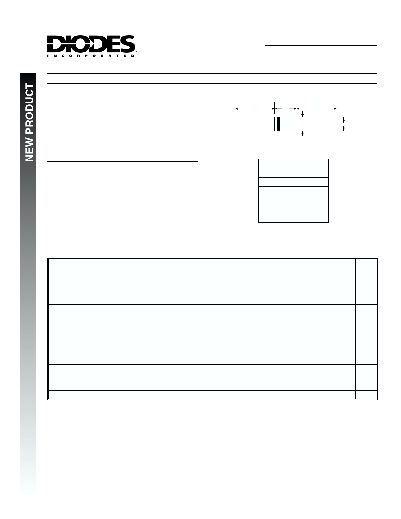
ABA
C
D
DO-201AD
Dim Min Max
A 25.40 ¾
B 7.20 9.50
C 1.20 1.30
D 4.80 5.30
All Dimensions in mm
Maximum Ratings and Electrical Characteristics
Single phase, half wave, 60Hz, resistive or inductive load.
For capacitive load, derate current by 20%.
Characteristic
Symbol
Peak Repetitive Reverse Voltage
Working Peak Reverse Voltage
DC Blocking Voltage
VRRM
VRWM
VR
RMS Reverse Voltage
VR(RMS)
Average Rectified Output Current
@ TT = 40°C
IO
Non-Repetitive Peak Forward Surge Current
8.3ms Single half sine-wave Superimposed on Rated Load
(JEDEC Method)
IFSM
Forward Voltage
@ IF = 3.0A, TJ = 150°C
@ IF = 3.0A, TJ = 25°C
@ IF = 4.0A, TJ = 25°C
VFM
Peak Reverse Current
at Rated DC Blocking Voltage
@ TA = 25°C
@ TA = 150°C
IRM
Reverse Recovery Time (Note 2)
trr
Forward Recovery Time (Note 3)
tfr
Typical Junction Capacitance (Note 1)
Cj
Typical Thermal Resistance, Junction to Ambient (Note 4) RqJA
Operating and Storage Temperature Range
Tj, TSTG
Notes:
1. Measured at 1.0MHz and applied reverse voltage of 4V DC.
2. Measured with IF = 0.5A, IR = 1.0A, Irr = 0.25A. See Figure 5.
3. Measured with IF = 1.0A, di/dt = 100A/ms, Duty Cycle £ 2.0%.
4. Mounted to PCB, lead length = 9.5mm.
@ TA = 25°C unless otherwise specified
MUR460
600
424
4.0
70
1.05
1.25
1.28
10
250
50
50
75
52
-65 to +175
Unit
V
V
A
A
V
mA
ns
ns
pF
K/W
°C
DS30183 Rev. A-0
1 of 2
MUR460
1 page | ||
| Páginas | Total 2 Páginas | |
| PDF Descargar | [ Datasheet MUR460.PDF ] | |
Hoja de datos destacado
| Número de pieza | Descripción | Fabricantes |
| MUR460 | HIGH EFFICIENCY GLASS PASSIVATED RECTIFIER | GOOD ELECTRONIC |
| MUR460 | 4 AMP ULTRA FAST RECTIFIER | Digitron Semiconductors |
| MUR460 | 40A SUPER-FAST RECTIFIER | Diodes Incorporated |
| MUR460 | (MUR405 - MUR4100) 4 Amp Super Fast Recovery Rectifier 50 to 1000 Volts | Micro Commercial Components |
| Número de pieza | Descripción | Fabricantes |
| SLA6805M | High Voltage 3 phase Motor Driver IC. |
Sanken |
| SDC1742 | 12- and 14-Bit Hybrid Synchro / Resolver-to-Digital Converters. |
Analog Devices |
|
DataSheet.es es una pagina web que funciona como un repositorio de manuales o hoja de datos de muchos de los productos más populares, |
| DataSheet.es | 2020 | Privacy Policy | Contacto | Buscar |