|
|
|
PDF IRU3021M Data sheet ( Hoja de datos )
| Número de pieza | IRU3021M | |
| Descripción | 5-BIT PROGRAMMABLE SYNCHRONOUS BUCK PLUS TRIPLE LDO CONTROLLER | |
| Fabricantes | International Rectifier | |
| Logotipo | ||
Hay una vista previa y un enlace de descarga de IRU3021M (archivo pdf) en la parte inferior de esta página. Total 8 Páginas | ||
|
No Preview Available !
Data Sheet No. PD94145
IRU3021M
5-BIT PROGRAMMABLE SYNCHRONOUS BUCK
PLUS TRIPLE LDO CONTROLLER
FEATURES
Provides single chip solution for Vcore, GTL+,
AGP bus, and 1.8V
Automatic voltage selection for AGP slot VDDQ
supply
Linear Regulator Controller On-Board for 1.8V
Designed to meet Intel latest VRM specification
for next generation microprocessors
On-Board DAC programs the output voltage from
1.3V to 3.5V
Linear Regulator Controller On-Board for 1.5V
GTL+ Supply
Loss-less Short Circuit Protection for all Outputs
Synchronous operation allows maximum effi-
ciency
Patented architecture allows fixed frequency
operation as well as 100% duty cycle during
dynamic load
Minimum Part Count
Soft-Start
High current totem pole driver for direct driving of
the external Power MOSFET
Power Good function monitors all outputs
Over-Voltage Protection Circuitry Protects the
switcher output and generates a Fault output
APPLICATIONS
Total Power Solution for next generation Intel
processor application
DESCRIPTION
The IRU3021M controller IC is specifically designed to
meet Intel specification for next generation microproces-
sor applications requiring multiple on-board regulators.
The IRU3021M provides a single chip controller IC for
the Vcore, three LDO controllers, one with an automatic
select pin that connects to the Type Detect pin of the
AGP slot for the AGP VDDQ supply, one for GTL+ and
the other for the 1.8V chip set regulator as required for
the next generation PC applications. The IRU3021M uses
N-channel MOSFET as pass transistor for Vout2(VDDQ),
Vout3(1.5V) and Vout4(1.8V). No external resistor di-
vider is necessary for any of the regulators. The switch-
ing regulator feature a patented topology that in combi-
nation with a few external components as shown in the
typical application circuit, will provide well in excess of
20A of output current for an on-board DC/DC converter
while automatically providing the right output voltage via
the 5-bit internal DAC .The IRU3021M also features, loss-
less current sensing for both switcher by using the RDS(on)
of the high-side power MOSFET as the sensing resistor,
an output under-voltage shutdown that detects short cir-
cuit condition for the linear outputs and latches the sys-
tem off, and a Power Good window comparator that
switches its open collector output low when any one of
the outputs is outside of a pre-programmed window.
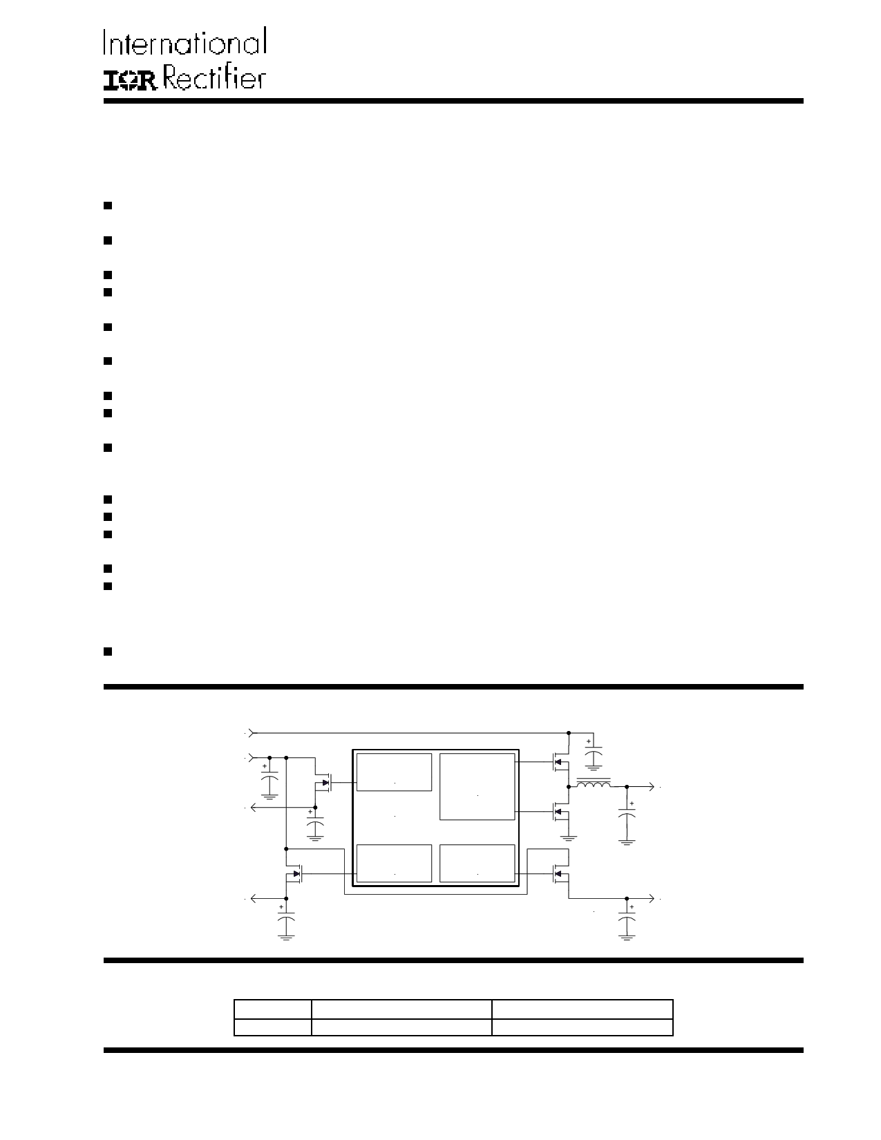
TYPICAL APPLICATION
5V
3.3V
LINEAR
CONTROL
Vout2
IRU3021M
SWITCHER
CONTROL
Vout1
Vout3
LINEAR
CONTROL
LINEAR
CONTROL
3021Mapp3-1.1
Figure 1 - Typical application of the IRU3021M.
Vout4
PACKAGE ORDER INFORMATION
TA (!C)
0 To 70
DEVICE
IRU3021MCW
PACKAGE
28-Pin Plastic SOIC WB
Rev. 1.4
07/24/01
1
1 page 
IRU3021M
PIN# PIN SYMBOL
9 SD
10 Vsen2
11 Select
12 SS
13 Fault / Rt
14 Vsen4
15 Drive4
16 NC
17 Gnd
18 Drive3
19 Vsen3
20 V5
21 Fb
22 Vsen1
23 OCSet
24 PGnd
25 LGate
26 Phase
27 UGate
28 V12
PIN DESCRIPTION
This pin provides shutdown for all the regulators. A TTL compatible, logic level high applied
to this pin disables all the outputs and discharges the soft-start capacitor. The SD signal
turns off the synchronous MOSFET allowing body diode to conduct and discharge the
output capacitor.
This pin provides the feedback for the AGP linear regulator. The Select pin when con-
nected to the "Type Detect" pin of the AGP slot automatically selects the right voltage for
the AGP VDDQ.
This pin provides automatic voltage selection for the AGP switching regulator. When it is
pulled LO, the voltage is 1.5V and when left open or pulled to HI, the voltage is 3.3V.
This pin provides the soft-start for all the regulators. An internal current source charges an
external capacitor that is connected from this pin to ground which ramps up the outputs of
the regulators, preventing the outputs from overshooting as well as limiting the input cur-
rent. The second function of the Soft-Start cap is to provide long off time (HICCUP) for the
synchronous MOSFET during current limiting.
This pin has dual function. It acts as an output of the over-voltage protection circuitry or it
can be used to program the frequency using an external resistor. When used as a fault
detector, if any of the switcher outputs exceed the OVP trip point, the Fault pin switches
to 12V and the soft-start cap is discharged. If the Fault pin is to be connected to any
external circuitry, it needs to be buffered.
This pin provides the feedback for the linear regulator that its output drive is Drive4.
This pin controls the gate of an external MOSFET for the 1.8V chip set linear regulator.
This pin is not connected internally.
This pin serves as the ground pin and must be connected directly to the ground plane.
This pin controls the gate of an external transistor for the 1.5V GTL+ linear regulator.
This pin provides the feedback for the linear regulator that its output drive is Drive3.
5V supply voltage. A high frequency capacitor (0.1 to 1µF) must be placed close to this
pin and connected from this pin to the ground plane for noise free operation.
This pin provides the feedback for the synchronous switching regulator. Typically this pin
can be connected directly to the output of the switching regulator. However, a resistor
divider is recommended to be connected from this pin to Vout1 and ground to adjust the
output voltage for any drop in the output voltage that is caused by the trace resistance.
The value of the resistor connected from Vout1 to Fb1 must be less than 1000Ω.
This pin is internally connected to the under-voltage and over-voltage comparators sens-
ing the Vcore status. It must be connected directly to the Vcore supply.
This pin is connected to the Drain of the power MOSFET of the Core supply and it provides
the positive sensing for the internal current sensing circuitry. An external resistor pro-
grams the current sense threshold depending on the RDS of the power MOSFET. An
external capacitor is placed in parallel with the programming resistor to provide high fre-
quency noise filtering.
This pin serves as the Power ground pin and must be connected directly to the ground
plane close to the source of the synchronous MOSFET. A high frequency capacitor (typi-
cally 1µF) must be connected from V12 pin to this pin for noise free operation.
Output driver for the synchronous power MOSFET for the Core supply.
This pin is connected to the source of the power MOSFET for the Core supply and it
provides the negative sensing for the internal current sensing circuitry.
Output driver for the high side power MOSFET for the Core supply.
This pin is connected to the 12V supply and serves as the power Vcc pin for the output
drivers. A high frequency capacitor (typically 1µF) must be placed close to this pin and
PGnd pin and be connected directly from this pin to the ground plane for the noise free
operation.
Rev. 1.4
07/24/01
5
5 Page | ||
| Páginas | Total 8 Páginas | |
| PDF Descargar | [ Datasheet IRU3021M.PDF ] | |
Hoja de datos destacado
| Número de pieza | Descripción | Fabricantes |
| IRU3021M | 5-BIT PROGRAMMABLE SYNCHRONOUS BUCK PLUS TRIPLE LDO CONTROLLER | International Rectifier |
| Número de pieza | Descripción | Fabricantes |
| SLA6805M | High Voltage 3 phase Motor Driver IC. |
Sanken |
| SDC1742 | 12- and 14-Bit Hybrid Synchro / Resolver-to-Digital Converters. |
Analog Devices |
|
DataSheet.es es una pagina web que funciona como un repositorio de manuales o hoja de datos de muchos de los productos más populares, |
| DataSheet.es | 2020 | Privacy Policy | Contacto | Buscar |