|
|
|
PDF NJW1107 Data sheet ( Hoja de datos )
| Número de pieza | NJW1107 | |
| Descripción | Dolby Pro Logic Surround Decoder with Discrete 5.1ch Input | |
| Fabricantes | New Japan Radio | |
| Logotipo | ||
Hay una vista previa y un enlace de descarga de NJW1107 (archivo pdf) en la parte inferior de esta página. Total 12 Páginas | ||
|
No Preview Available !
NJW1107
PRELIMINARY
Dolby Pro Logic Surround Decoder with Discrete 5.1ch Input
s GENERAL DESCRIPTION
The NJW1107 is a Dolby Pro Logic Surround Decoder with discrete
5.1ch input. It includes Dolby Pro Logic Surround decoder, 4 master
volumes, 4 level trimmers and 6 switches.
The 6 switches choose internal Dolby Pro Logic Surround Decoder
or discrete 5.1ch inputs. The NJW1107 is most suitable for AV
amplifier with discrete 5.1ch inputs for Dolby Digital.
In addition to Dolby Pro Logic Surround function, the NJW1107
performs easily other surround function such as Hall, Live, Disco and
others, and echo and microphone mixing functions for Karaoke.
s PACKAGE OUTLINE
NJW1107FC3
Dolby and double-D symbol are trademarks of Dolby Laboratories Licensing Corporation.
San Francisco, CA94103-4813.USA.
This device is available only to licensees of Dolby Lab.
Licensing and application information may be obtained from Dolby Lab.
s FEATURES
q Operating Voltage: VCC=9V(Analog Block), VDD=5V(Digital Block)
q Digital Delay on chip
q Discrete 5.1ch Input for Dolby Digital
q Master Volume for Center, Surround and Subwoofer Channel: -79 to 0dB/1dB step (0dB = Dolby Level)
q Level Trimmer for Center, Surround and Subwoofer Channel: -31 to 0dB/1dB step (0dB = Dolby Level)
q Karaoke function (Echo, MIC mixing)
q Serial Data Interface (3-wire) DATA, REQ, SCK
q Bi-CMOS Technology
q Package Outline
QFP80
s FUNCTION
[Dolby Pro Logic Surround]
q Automatic input balance
q Noise sequencer
q Adaptive matrix
q Center mode control (Wide, Normal, Phantom, Off)
q Modified B-type noise reduction
q 7kHz low pass filter
q Dolby 3 stereo mode
q Digital time delay (15.4, 20.5, 25.6, 29.2ms)
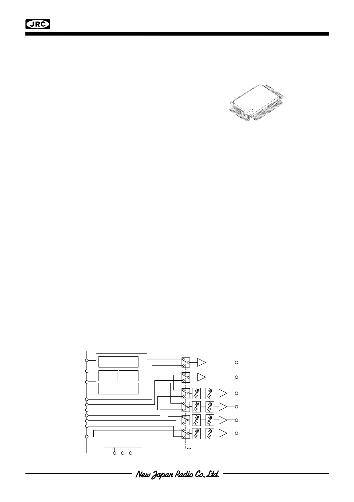
s SYSTEM BLOCK DIAGRAM
[Other Surround]
q Sound field control
q Front mixing control
q Digital time delay
(15.4, 20.5, 25.6, 29.2 51.2ms)
[Karaoke]
q Echo control
q MIC mixing
q Digital time delay (123, 184ms)
M ICIN
LTIN
RTIN
LIN
RIN
CIN
SLIN
SRIN
SWIN
normal
SWIN
Pro Logic
Digital
Re ar
Surround Stereo
Echo
L
R
C
SL
SR
MCU
Interface
LOUT
M aster
Trimmer Vol
ROUT
COUT
SLOUT
SROUT
SWOUT
Dolby Pro Logic
Discr ete 5.1ch (ex. Dolby Digital)
( 1 / 11 ) C
1 page 
s APPLICATION CIRCUIT
NJW1107
C38
1000p
C37
4700p
C35
0.1u
C34 C33
0.22u 0.22u
C31
0.1u
C29
1000p
C28
4700p
C26
1u
C42
1u
ECHO
OUT
C41
1u
C43 5600p
C44 0.047u
R45 330k
C45 0.68u
C46 0.22u
C47 0.22u
C48 4.7u
C49 4.7u
C50 0.22u
C51 0.22u
C52 0.1u
C53 0.047u
C54 0.047u
C55 0.1u
C56 0.1u
C57 0.022u
C58 0.022u
C59 0.1u
C60 680p
RA60 150k R60 47k
C61 0.01u R61 75k
C62 680p
RA62 150k R62 47k
C63 0.01u R63 75k
C64
0.01u
C65
0.01u
DELAY
VOL
LPF
DO-SW
D/A A/D
LOGIC
F.B.
VOL
10kbit
SRAM
DI-SW
BNR-SW
L-R
L+R
2
CENT ER MODE
CONTROL
C
R
L
L R C S’
COM BINNING
NETWORKS
VCA
SEL ECTER
NOISE
SEQUENC ER
R-SW
L-SW
LPF
CLK
SW-SW
SR-SW
SL-SW
C-SW
DV SS
REQ
SCK
DATA
DV DD
AGND
C21 0.1u DVDD
+5V
M ICIN
C20
1u
SWBR-SW
SW
C18
0.1u
SWVOL
C17 OUT
10u
C15
10u
C14
10u
SRVOL
OUT
C12
SR 10u
SL
C10
10u
C9
10u SLVOL
OUT
C8
0.1u
C7
0.1u
C
C4
10u
CVOL
C3 10u OUT
R ROUT
C2 10u
L LOUT
C1 10u
( 5 / 11 ) C
5 Page 
NJW1107
s DATA TIMING
DATA
SCK
REQ
t1,t2
t6
t1
t7
t4
t2
t5
t3
PARAMETER
Signal rise time
Signal fall time
SCK clock width
SCK “H” pulse width
SCK “L” pulse width
DATA setup time
DATA hold time
REQ rise hold time
REQ “H” pulse width
SCK setup time
SYMBOL
t1
t2
t3
t4
t5
t6
t7
t8
t9
t10
2.2V
0.8V
VDD=5V
t10
t8 t9
t1 t2
2.2V
0.8V
2.2V
0.8V
TEST CONDITION
MIN.
TYP. MAX. UNIT
- - 0.5
0.5
2
0.8 -
-
0.8 -
0.8 -
-
-
µs
0.8 -
-
1.6 -
-
0.8 -
-
1.6 -
-
s NOTICE
The NJW1107 includes Auto-Reset circuit. The NJW1107 requires both analog power supply (AVCC) and digital
power supply (DVDD). Internal digital circuits are initialized by AVCC. The internal reset signal is released after treset
period (0.7sec. < treset < 1.3sec.).
• Power-on Sequence
1. Turn the AVCC on first.
2. Provide the DVDD within 0.7 seconds after the AVCC turns on.
3. Keep the voltage of DVDD below the voltage of AVCC always.
4. Wait for 1.3 seconds and over after the AVCC turns on.
5. Transmit the control data from MCU.
AVCC
(AVCC>DVDD)
DVDD
Internal
reset signal
treset
automatic reset cancel
( 11 / 11 ) C
11 Page | ||
| Páginas | Total 12 Páginas | |
| PDF Descargar | [ Datasheet NJW1107.PDF ] | |
Hoja de datos destacado
| Número de pieza | Descripción | Fabricantes |
| NJW1102 | DOLBY PRO LOGIC SURROUND DECODER | New Japan Radio |
| NJW1102A | DOLBY PRO LOGIC SURROUND DECODER | New Japan Radio |
| NJW1103 | DOLBY PRO LOGIC SURROUND DECODER | New Japan Radio |
| NJW1104 | DOLBY PRO LOGIC SURROUND DECODER | New Japan Radio |
| Número de pieza | Descripción | Fabricantes |
| SLA6805M | High Voltage 3 phase Motor Driver IC. |
Sanken |
| SDC1742 | 12- and 14-Bit Hybrid Synchro / Resolver-to-Digital Converters. |
Analog Devices |
|
DataSheet.es es una pagina web que funciona como un repositorio de manuales o hoja de datos de muchos de los productos más populares, |
| DataSheet.es | 2020 | Privacy Policy | Contacto | Buscar |