|
|
|
PDF U4223B-MFSG3 Data sheet ( Hoja de datos )
| Número de pieza | U4223B-MFSG3 | |
| Descripción | Time-Code Receiver with A/D Converter | |
| Fabricantes | ATMEL Corporation | |
| Logotipo | ||
Hay una vista previa y un enlace de descarga de U4223B-MFSG3 (archivo pdf) en la parte inferior de esta página. Total 18 Páginas | ||
|
No Preview Available !
Time-Code Receiver with A/D Converter
U4223B
Description
The U4223B is a bipolar integrated straight-through receiver circuit in the frequency range of 40 kHz to 80 kHz.
The device is designed for radio-controlled clock applications.
Features
D Very low power consumption
D Very high sensitivity
D High selectivity by using two crystal filters
D Power-down mode available
D Only a few external components necessary
D 4-bit digital output
D AGC hold mode
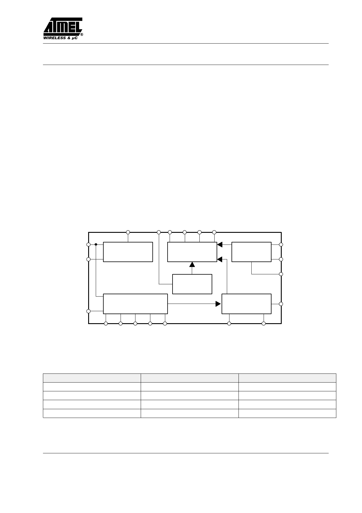
Block Diagram
PON CLK D3 D2 D1 D0
VCC 1
GND
3
IN 2
16
Power supply
12 17 18 19
ADC
AGC
amplifier
Impulse
circuit
4 5 6 14 15
SB Q1A Q1B Q2A Q2B
20 11 FLB
Decoder
10 FLA
9 DEC
Rectifier & 13
integrator
78
REC INT
SL
Figure 1. Block diagram
Ordering and Package Information
Extended Type Number
U4223B-MFS
U4223B-MFSG3
T4223B-MF
T4223B-MC
Package
SSO20 plastic
SSO20 plastic
No
No
Remarks
Taping according to IEC-286-3
Die on foil
Die on carrier
Rev. A7, 06-Mar-01
1 (18)
1 page 
U4223B
Vclk
mV
100
50
0
4 7 8 11 12 t/ms
Now, the time-code
signal can be read
Falling edge initiates
time-code conversion
Now, the AGC value can be read
Rising edge initiates
AGC signal conversion
Thus, the first step in designing the antenna circuit is to
measure the bandwidth. Figure 17 shows an example for
the test circuit. The RF signal is coupled into the bar
antenna by inductive means, e.g., a wire loop. It can be
measured by a simple oscilloscope using the 10:1 probe.
The input capacitance of the probe, typically about 10 pF,
should be taken into consideration. By varying the fre-
quency of the signal generator, the resonant frequency
can be determined.
RF signal
generator
77.5 kHz
Scope
Figure 14.
In order to minimize interferences, we recommend a
voltage swing of about 100 mV. A full supply-voltage
swing is possible but reduces the sensitivity.
VCC
CLK
GND
Figure 15.
Please note:
The signals and voltages at the Pins REC, INT, FLA,
FLB, Q1A, Q1B, Q2A and Q2B cannot be measured by
standard measurement equipment due to very high inter-
nal impedances. For the same reason, the PCB should be
protected against surface humidity.
Design Hints for the Ferrite Antenna
The bar antenna is a very critical device of the complete
clock receiver. Observing some basic RF design rules
helps to avoid possible problems. The IC requires a reso-
nant resistance of 50 kW to 200 kW. This can be achieved
by a variation of the L/C-relation in the antenna circuit.
It is not easy to measure such high resistances in the RF
region. A more convenient way is to distinguish between
the different bandwidths of the antenna circuit and to cal-
culate the resonant resistance afterwards.
wire loop
Cres
Probe
10 : 1
w10 MW
Figure 16.
At the point where the voltage of the RF signal at the
probe drops by 3 dB, the two frequencies can then be
measured. The difference between these two frequencies
is called the bandwidth BWA of the antenna circuit. As the
value of the capacitor Cres in the antenna circuit is known,
it is easy to compute the resonant resistance according to
the following formula:
Rres + 2
1
p BWA Cres
where
Rres is the resonant resistance,
BWA is the measured bandwidth (in Hz)
Cres is the value of the capacitor in the antenna circuit
(in Farad).
If high inductance values and low capacitor values are
used, the additional parasitic capacitances of the coil
(v20 pF) must be considered. The Q value of the capa-
citor should be no problem if a high Q type is used. The
Q value of the coil differs more or less from the DC
resistance of the wire. Skin effects can be observed but do
not dominate.
Therefore, it should not be a problem to achieve the
recommended values of the resonant resistance. The use
of thicker wire increases the Q value and accordingly
reduces bandwidth. This is advantageous in order to
improve reception in noisy areas. On the other hand,
temperature compensation of the resonant frequency
might become a problem if the bandwidth of the antenna
circuit is low compared to the temperature variation of the
resonant frequency. Of course, the Q value can also be
reduced by a parallel resistor.
Rev. A7, 06-Mar-01
5 (18)
5 Page 
U4223B
Application Circuit for JG2AS 40 kHz
+VCC
Control lines
Ferrite
Antenna
fres = 40 kHz
1
2
3
4
40 kHz 2)
5
6
C1
680 pF
220 nF
C2
7
1 MW
8
R
9
C3
10 nF
10
U4223B
20 D0
10 nF
19 D1
10 nF
18 D2
10 nF
D3
17
10 nF PON 3)
16
40 kHz
15
Microcomputer
14
SL 1)
13
12
11
Figure 22.
CLK 4)
Display
Keyboard
1) If SL is not used, SL is connected to VCC
2) 40-kHz crystal can be replaced by 22 pF
3) If IC is activated, PON is connected to GND
4) Voltage swing 100 mVpp at Pin 12
Rev. A7, 06-Mar-01
11 (18)
11 Page | ||
| Páginas | Total 18 Páginas | |
| PDF Descargar | [ Datasheet U4223B-MFSG3.PDF ] | |
Hoja de datos destacado
| Número de pieza | Descripción | Fabricantes |
| U4223B-MFSG3 | Time-Code Receiver with A/D Converter | ATMEL Corporation |
| Número de pieza | Descripción | Fabricantes |
| SLA6805M | High Voltage 3 phase Motor Driver IC. |
Sanken |
| SDC1742 | 12- and 14-Bit Hybrid Synchro / Resolver-to-Digital Converters. |
Analog Devices |
|
DataSheet.es es una pagina web que funciona como un repositorio de manuales o hoja de datos de muchos de los productos más populares, |
| DataSheet.es | 2020 | Privacy Policy | Contacto | Buscar |